166 Rockwell Automation Publication 2099-UM001D-EN-P - December 2012
Appendix B Interconnect Diagrams
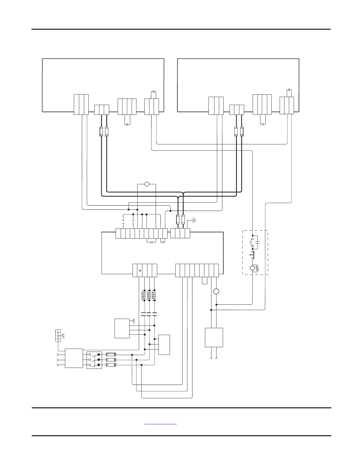
Figure 75 - 8720MC-RPS065BM Regenerative Power Supply to Multiple Kinetix 7000 Drives
This configuration requires the power regenerative mode settings as described in the 8720MC Regenerative Power Supply
Installation Manual, publication 8720MC-RM001
, and setting of the power tab in RSLogix 5000 software is set to the
appropriate bus regulator catalog number. Common mode capacitors should be disconnected on DC common bus drives.
2
5
6
8
7
2
5
6
8
7
L1
L2
L3
TB1
L1 AUX
L2 AUX
L3 AUX
PR1
PR2
PR3
MC1
MC2
TB2
TB1
DC+
DC-
GND
DC+
DC-
TB
24V DC
ENABLE
24V COM
IOD - Axis 1
GPR2+
GPR2-
GPR - Axis 1
REGEN COM
REGEN OK
GPIO - Axis 1
DC+
DC-
TB
GPR2+
GPR2-
GPR - Axis n
REGEN COM
REGEN OK
GPIO - Axis n
24V DC
ENABLE
24V COM
IOD - Axis n
STOP* START (RPS On)*
CR1*
CR1*
CR1*
MC
E/N
1
1
CR2*
See
Note 11
CR2*
See
Note 11
RPS Stop-Start String*
Regenerative
Power Supply
8720MC-RPS065BM
*120V/240V AC
or
24V DC
* Indicates User Supplied Component
Three-phase
Contactor (MC)
*Bonded Cabinet
Ground Bus
*Harmonic
Filter
*Vari sto r
Control
Stop String
See Notes 6 and 8
DC Bus
Connections
Power
Connections
DC Bus
Connections
Power
Connections
*Single- phase
AC Line Filter
See Note 3
Kinetix 7000 Drive
2099-BMxx-S
*DC Line
Fuses
*Line Reactor
(8720MC for
RPS unit)
*Three-phase
AC Line Filter
for Main Power
See Note 3
* DC Line Fuses
(see table in
Appendix A)
* DC Line Fuses
(see table in
Appendix A)
MC
RST
PWR
0V
24V
COM
IP
RDY
FR
FR
TB3
Fault Relay
Contact
*MC AUX
*Circuit
Breaker
*Input
Fusing
*Three-phase Input
(+10/-15%)
380V AC RMS, 50 Hz
or 460V AC RMS, 60 Hz
See Note 1
Additional connections required, but not
shown in this diagram:
1. +24V DC Control Power
2. Motor Feedback, Brake (if used), and Power
3. Drive I/O and Communications
Control
Stop String
See Notes 6 and 8
Kinetix 7000 Drive
2099-BMxx-S
See Note 4
CR2*
 Loading...


