Rockwell Automation Publication 2099-UM001D-EN-P - December 2012 177
Interconnect Diagrams Appendix B
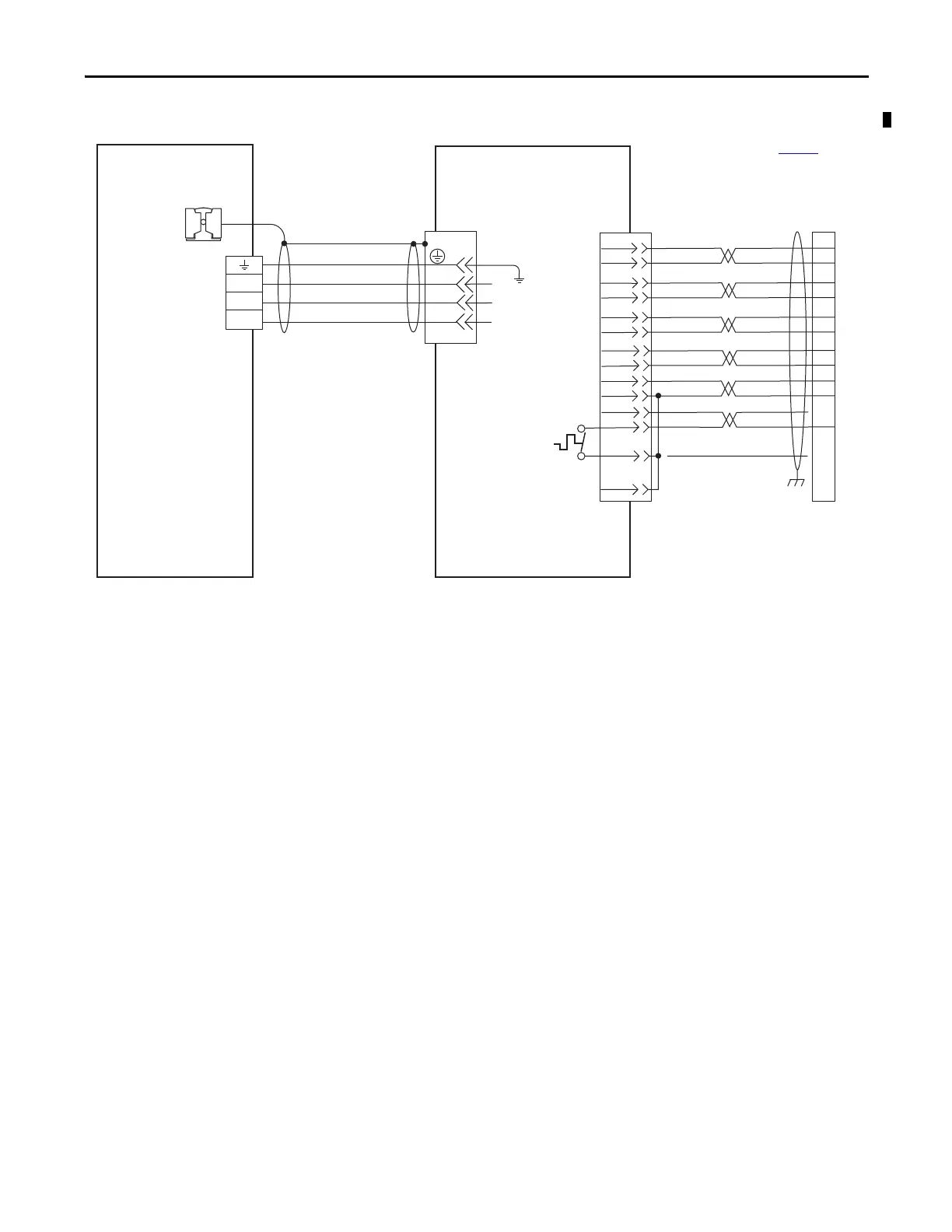
Figure 86 - Example with RDD-Series (Bulletin RDB-B) Motors
C/W
B/V
A/U
W
V
U
SIN+
SIN-
COS+
COS-
DATA+
DATA-
+5VDC
ECOM
GREEN
WHT/GREEN
GRAY
WHT/GRAY
BLACK
WHT/BLACK
RED
WHT/RED
3
4
5
6
1
2
9
10
1
2
3
4
9
10
7
8
14
12
ORANGE
WHT/ORANGE
11
13
11
4
3
2
1
Green/Yellow
Blue
Black
Brown
GND
Shield
W
V
U
TS-
COM
BLUE
7
8
5
6
CLK+
CLK-
BROWN
WHT/BROWN
–
TS+
Motor Power
(MP) Connector
Cable Shield
Clamp
RDB-Bxxxx Direct Drive
Servo Motors with
High Resolution Feedback
Motor Feedback
(MF) Connector
Three-phase
Motor Power
Motor
Feedback
Thermistor
2090-K7CK-KENDAT
Feedback Module
Refer to table on page 162 for
note information.
2090-XXNFMF-Sxx (standard, non-flex) or
2090-CFBM7DF-CDAFxx (continuous-flex)
Flying-lead Feedback Cable
2090-CPWM7DF-xxAAxx, or
2090-XXNPMF-xxSxx
(standard, non-flex)
or 2090-CPWM7DF-xxAFxx
(continuous-flex)
Motor Power Cable
Kinetix 7000 Drive
Cable shield clamp must be
used in order to meet CE
requirements. No external
connection to ground is
required.
 Loading...


