40 Rockwell Automation Publication 2099-UM001D-EN-P - December 2012
Chapter 2 Install the Kinetix 7000 Drive System
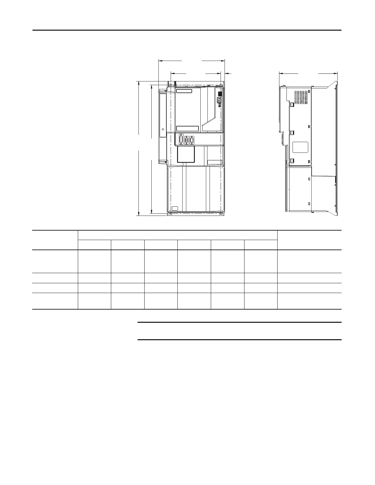
Figure 16 - Kinetix 7000 Approximate Mounting Dimensions
B
C
M1
M2 M3
A
2099-BM07 shown
Kinetix 7000 Drive
Cat. No.
Dimensions in mm (in.)
Mounting Screw SizeA B C M1M2M3
2099-BM06-S
2099-BM07-S
2099-BM08-S
517.5 (20.37) 254.12 (10.0) 224.3 (8.83) 495.0 (19.49) 192.0 (7.56) 15.3 (0.60) M6 (0.25)
2099-BM09-S 644.5 (25.37) 331.9 (13.07) 286.7 (11.29) 625.0 (24.61) 225.0 (8.86) 37.5 (1.48) M6 (0.25)
2099-BM10-S 690.3 (38.47) 331.9 (13.07) 286.7 (11.29) 625.0 (24.61) 225.0 (8.86) 37.5 (1.48) M6 (0.25)
2099-BM11-S
2099-BM12-S
977.1 (38.47) 429.2 (16.90) 282.7 (11.13) 824.0 (32.44) 300.0 (11.81) 49.6 (1.95) M8 (0.3125)
Each Kinetix 7000 drive requires four mounting screws.
 Loading...


