Rockwell Automation Publication 2099-UM001D-EN-P - December 2012 69
Kinetix 7000 Connector Data Chapter 3
• See the Kinetix Motion Control Selection Guide, publication GMC-
SG001, for cables compatible with the Kinetix 7000 drive and motor.
• Low profile connector let you develop a custom cable for the Motor
Feedback (MF) or Auxiliary Feedback (AF) connectors.
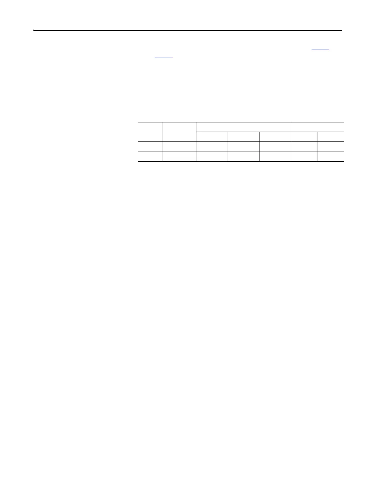
The following table details power supply specifications for the motor and
auxiliary feedback connectors.
Table 29 - Motor and Auxiliary Feedback Power Supply Specifications
Power
Supply
Signal Name Voltage (V DC) Current (mA)
Min Nom Max Min Max
+5V EPWR_5V 5.13 5.4 5.67 10 400
(1)
(3)
(1) 400 mA on the 5V supply split in any manner between the channels with no load on the 5V supply.
+9V EPWR_9V 8.3 9.1 9.9 10 275
(2)
(3)
(2) 275 mA on the 9V supply split in any manner between the channels with no load on the 9V supply.
(3) 300 mA on the 5V supply on one channel with 150 mA on the 9V supply on the second channel.
 Loading...


