Design a sequential function chart
18 Rockwell Automation Publication 1756-PM006I-EN-P - February 2018
The first step in the development of an SFC is to separate the configuration and
regulation of devices from the commands to those devices. Logix 5000 controllers
let you divide your project into one continuous task and multiple periodic tasks
and event tasks.
1. Organize your project.
These functions Go into this type of task
• Configure and regulate devices
Periodic task
Command a device to a specific state
• Sequence the execution of your process
SFC in the continuous task
2. For those functions that go in a periodic task, group the functions according
to similar update rates. Create a periodic task for each update rate.
For example, 2-state devices may require faster updates than PID loops. Use
separate periodic tasks for each.
In this example, a project uses two periodic tasks to regulate motors, valves,
and temperature loops. An SFC controls the process.
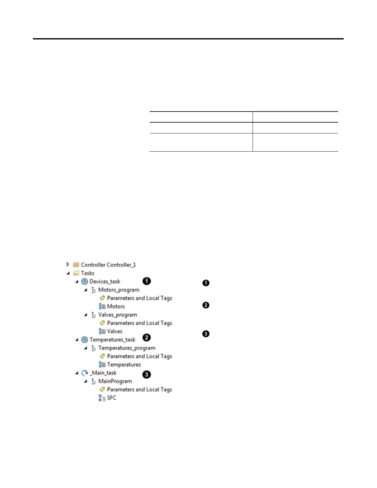
Example
Define the Tasks:
This task (periodic) uses Function Block diagrams to turn on or off motors
and open or close valves. The SFC in MainTask commands the state for
each device. The Function Block diagrams set and maintain that state.
This task (periodic) uses Function Block diagrams to configure and
regulate temperature loops. The SFC in MainTask commands the
temperatures. The Function Block diagrams set and maintain those
temperatures.
This task (continuous) executes the sequential function chart (SFC). The
SFC commands the specific state or temperature for each device or
temperature loop.
 Loading...

