112 Rockwell Automation Publication 2711P-UM006A-EN-P - November 2010
Chapter 6 Install and Replace Components
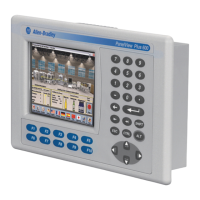
4. Lift the LCD display and detach the display connector from the circuit
board.
The circuit board layout may vary for each terminal model. The location
of the connector varies by model.
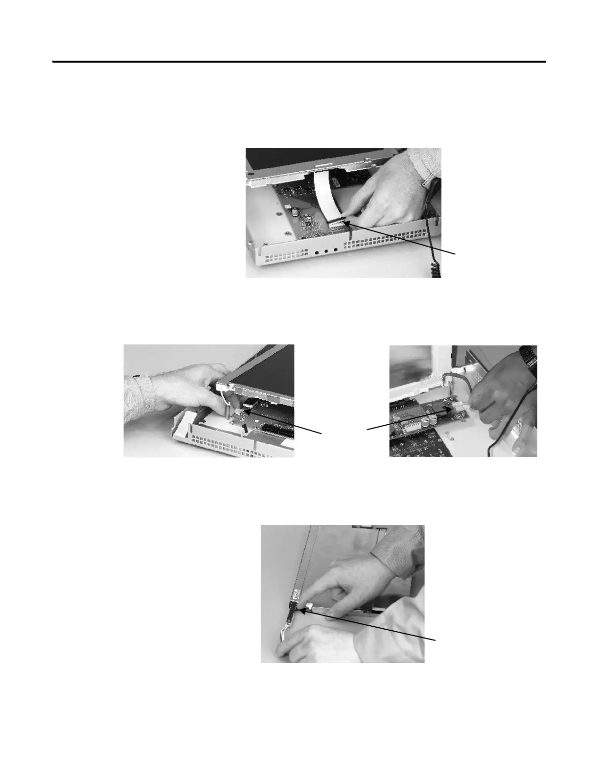
5. Detach the backlight connectors from the circuit board.
• The 1250 has one or two backlight connectors depending on the series
of the display.
• The 1500 has four backlight connectors.
6. Follow these steps for the 700 and 1000 displays.
a. Press the retaining tab that secures the backlight, then pull out the
backlight.
Display
Connector
Backlight
Connector
1250
1500
Backlight
Retaining Tab
 Loading...