Rockwell Automation Publication 2711P-UM006A-EN-P - November 2010 113
Install and Replace Components Chapter 6
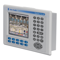
b. Insert the new backlight.
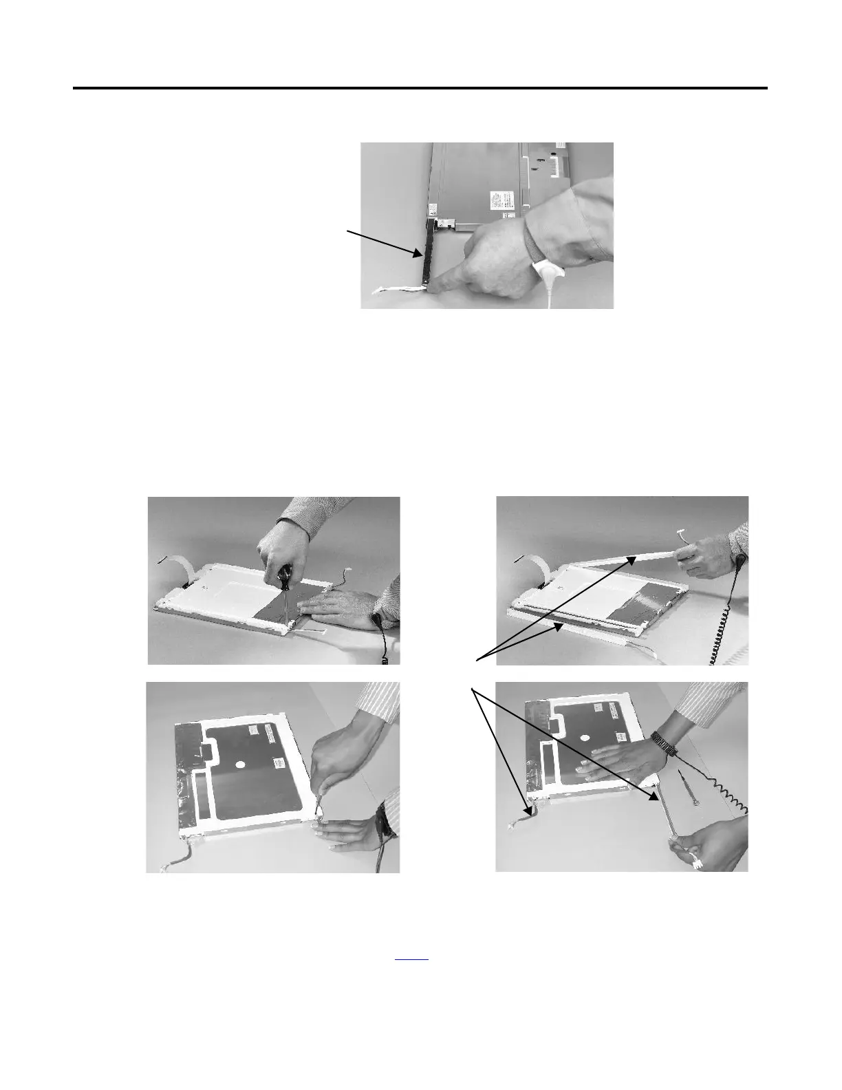
7. Follow these steps for the 1250 and 1500 displays.
a. Remove the screws that secure the backlights and remove the
backlights.
For the 1250 series A and B displays, the two backlights are each
secured with two screws. The single backlight for the 1250 series C
displays is secured with one screw.
For the 1500 series B displays, remove the tape, then remove the
backlights.
b. Insert the new backlights then secure each with the same screws from
the previous step, and torque to 0.117 N•m (1.04 lb•in).
8. Attach the LCD display connector to the circuit board.
Refer to step 4
.
Backlight
Backlights
1250
1500
 Loading...