Publication 1734-UM014A-EN-P - November 2010
10 Install Your Adapter
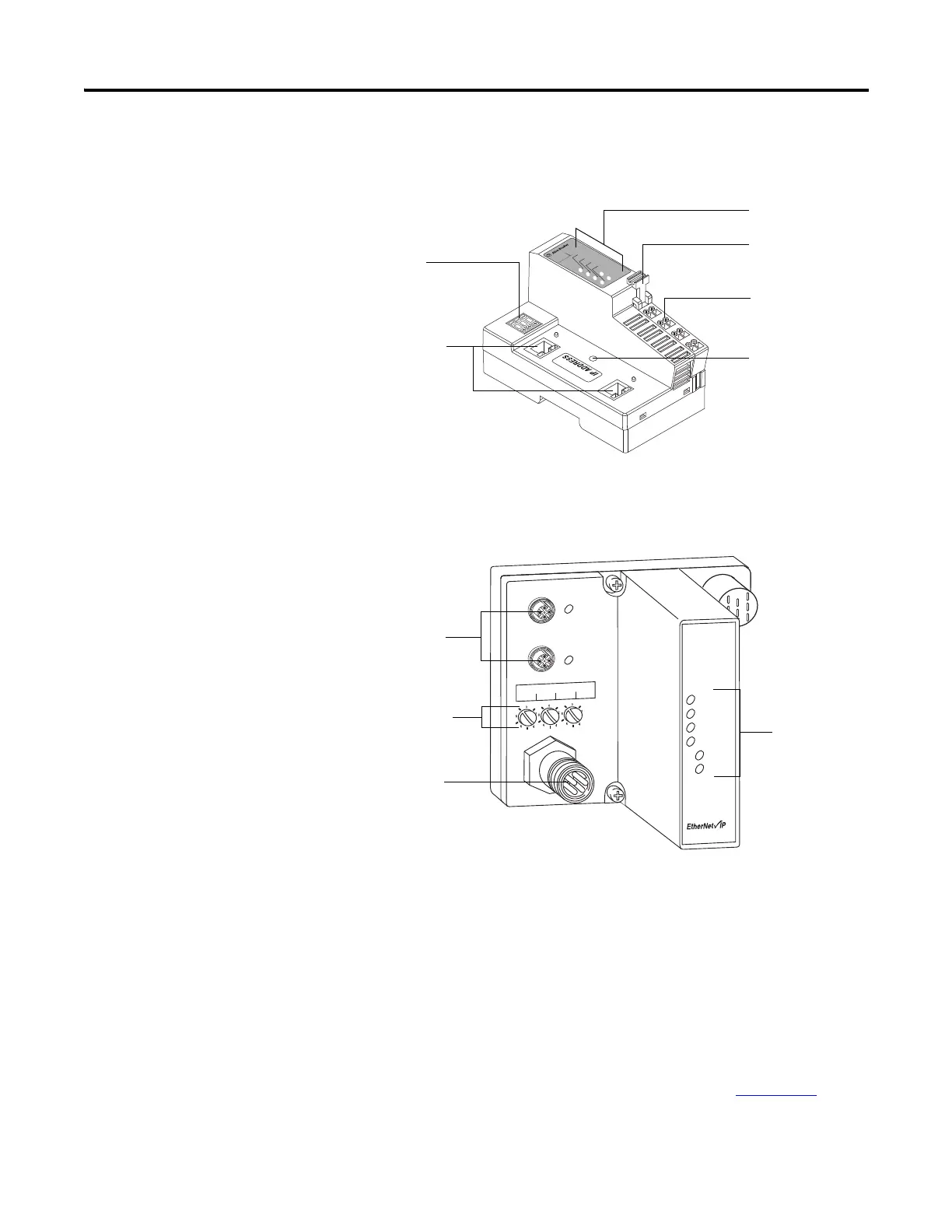
1734-AENTR Adapter
1738-AENTR Adapter
Mount the I/O Adapter
Use the following procedures to mount the I/O adapters on a new system
before you install any I/O modules.
Mount a 1734-FPD module in the slot next to the I/O adapter when applying
field power. You can also use the 24V DC to power the adapter to supply field
power, where no FPD is necessary. Refer to Point I/O Field Potential
Distribution Module Installation Instructions, publication 1734-IN059
for
more information.
1734-AENTR
Module
Status
Network
Activity
Network
Status
Point Bus
Status
System
Power
Field
Power
POINT I O
02
0
2
Link 2
Activity/
Status
3
4
5
6
7
Link 1
Activity/
Status
44849
Status indicators
RTB removal handle
Removable Terminal
Block (RTB)
DIN rail locking screw
(orange)
Ethernet network
RJ-45 connectors
Node address
thumbwheel
1738-AENTR
EtherNet I/P
Adapter
Status
Network
Activity
Network
Status
PointBus
Status
System
Power
Adapter
Power
conformance tested
™
PWR
IP ADDRESS
Link 2
Activity/
Status
Link 1
Activity/
Status
44830
M12 connectors
Auxiliary power
connector
Network address
switches
Status indicators

 Loading...


