Publication 1734-UM014A-EN-P - November 2010
64 Configure the Adapter for Direct Connection and Rack Optimization in RSLogix 5000 Software
Verify the Module
Chassis Size
You have now built the I/O tree and the RSLogix 5000 software uses the
chassis size from the General tab of the adapter for the rack-optimized I/O
connection. Now you need to configure this new chassis size value into the
adapter non-volatile memory. This procedure synchronizes the chassis size
value from the RSLogix 5000 software into the adapter hardware. You must be
online to perform this procedure.
1. Verify that the RSLogix 5000 software is online.
2. Right-click the name of the adapter under I/O Configuration in the
Project dialog.
3. Select Properties.
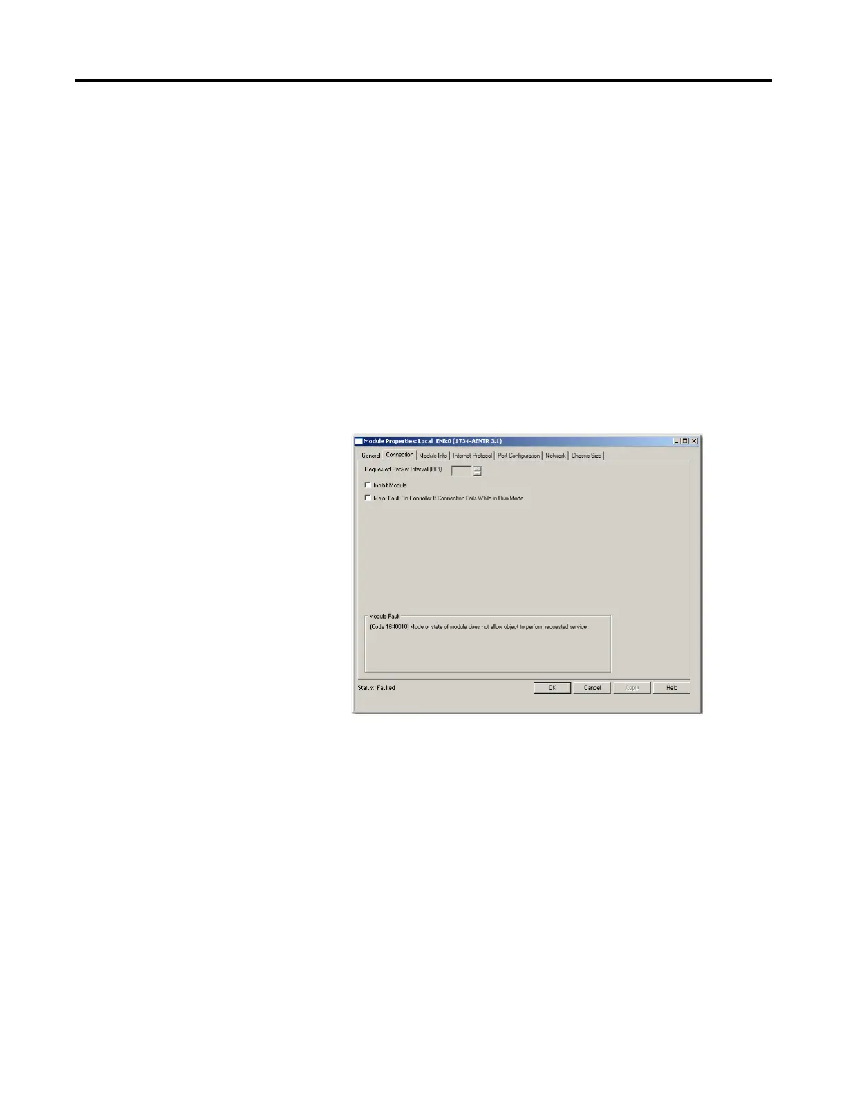
4. Click the Connection tab.
The Module Fault error code displays at the bottom of the
Connection tab.
5. Click the Chassis Size tab.

 Loading...


