Publication 1734-UM014A-EN-P - November 2010
50 Configure the Adapter for Direct Connection and Rack Optimization in RSLogix 5000 Software
Set Up the Hardware
The following section describe how to set up the I/O Hardware.
Set Up the POINT I/O Hardware
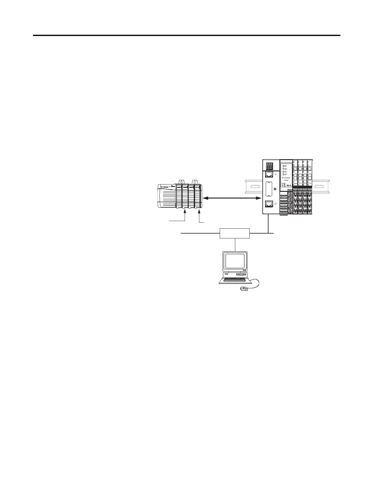
In this example, a ControlLogix chassis contains the L63 controller in slot 1
and a 1756-ENBT bridge module in slot 3. In this example, we mounted the
1734-AENTR adapter on a DIN rail in slot 0, with a 1734-OW2/C relay
output module in slot 1, a 1734-OV4E/C sink output module in slot 3, and
two other POINT I/O modules which will not be controlled by this Logix
controller in slots 2 and 4.
To work along with this example, set up your system as shown in the figure.
• Note that in the example application, the Logix controller and
1756-ENBT module (firmware revision 2.3 or later) we assume are in
the slots shown in the figure.
• Verify the IP addresses for your programming terminal, 1756-ENBT
module, and I/O adapter.
• Verify the position (slot) of the I/O modules on the DIN rail.
• Verify that you properly connected all wiring and cabling.
• Make sure you configured your communication driver (such as
AB_ETH-1 or AB-ETHIP-1) in the RSLinx software. SeeConfigure
the RSLinx Ethernet Communication Driver on page99.
Local
chassis
POINT I/O
L63
controller (slot 1)
1756-ENBT
10.88.70.4 (slot 3)
Data
Switch
10.88.70.26
Programming
terminal
Slot 0 1 2 3
1734-AENTR
10.88.70.2
Slot 0 1 2 3 4
Link 1
Activity/
Status
Link 2
Activity/
Status

 Loading...


