EasyManuals Logo

Allen-Bradley POINT I/O User Manual

Allen-Bradley POINT I/O
118 pages
To Next Page IconTo Next Page
To Previous Page IconTo Previous Page
Page #74 background imageLoading...
Page #74 background image
Publication 1734-UM014A-EN-P - November 2010
66 Configure the Adapter for Direct Connection and Rack Optimization in RSLogix 5000 Software
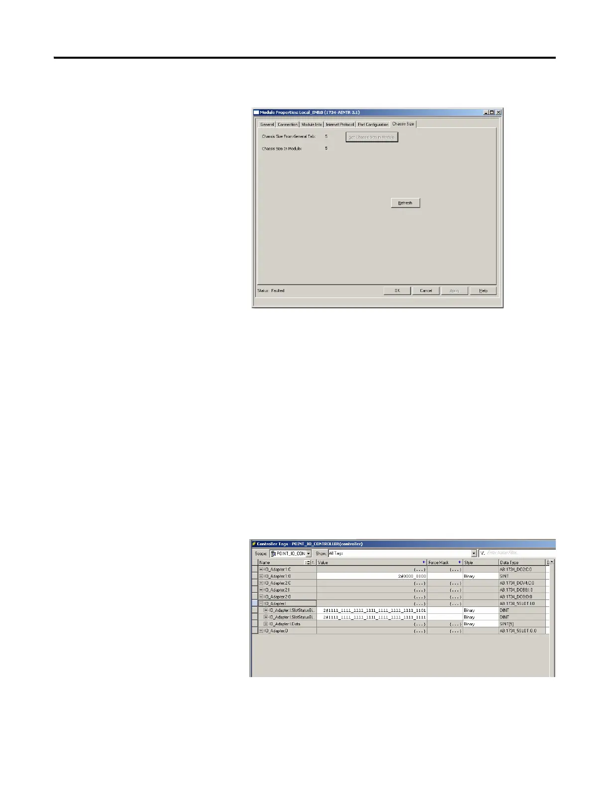
9. Notice the chassis size in the module is modified to 5.
10. Click OK.
At this point, your POINTBus status LED should be solid green. All
the yellow triangles in your I/O configuration should be gone.
11. Click OK to close the dialog.
12. Click File Save to save the project.
Access Module Data
Use the following information to use the I/O adapter data in the ladder logic
program:
POINT_IO_Adapter — the name you gave to your EtherNet adapter
# — slot number of POINT I/O module
C — configuration, I = input, O = output
Use the controller tags in your ladder program to read input data or write
output data.

Table of Contents

Questions and Answers:

Question and Answer IconNeed help?

Do you have a question about the Allen-Bradley POINT I/O and is the answer not in the manual?

Allen-Bradley POINT I/O Specifications

General IconGeneral
Power Supply24V DC
MountingDIN Rail
Wiring MethodRemovable terminal blocks
Communication ProtocolsEtherNet/IP, DeviceNet, ControlNet
Operating Temperature Range-20°C to 60°C (-4°F to 140°F)
Number of ChannelsVaries by module (e.g., 8, 16, 32)
CertificationsCE, cUL
TypeDigital and Analog I/O Modules
Output Voltage24V DC

Related product manuals