Publication 1734-UM014A-EN-P - November 2010
12 Install Your Adapter
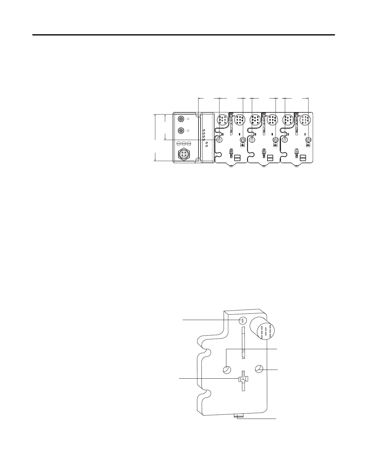
Refer to the drilling dimensions illustration for the ArmorPOINT I/O adapter
with I/O bases to guide you in mounting the adapter and I/O bases.
Drilling Dimensions
Install the mounting base as follows:
1. Lay out the required points as shown in the drilling dimension drawing.
2. Drill the necessary holes for #8 (M4) machine or self-tapping screws.
3. Mount the adapter using #8 (M4) screws.
4. Ground the system using the ground lug connection in the I/O base.
The ground lug connection is also a mounting hole.
5. Mount the terminating base that was shipped with the adapter as the last
base in the backplane instead of the base that was shipped with the
I/O module.
Terminal Base
46.25mm
(1.82in)
56.00mm
(2.20in)
102.0mm
(4.01in)
51.90mm
(2.04in)
20.10mm
(0.79in)
51.90mm
(2.04in)
51.90mm
(2.04in)
20.10mm
(0.79in)
43787
Mounting hole
Latching mechanism release
Ground connection
Keyswitch
Latching
mechanism hole

 Loading...


