Rockwell Automation Publication 6000-IN100A-EN-P - August 2020 49
Chapter 3 Drive Electrical Interconnection
Connect Isolation
Transformer Secondary
Power Cables
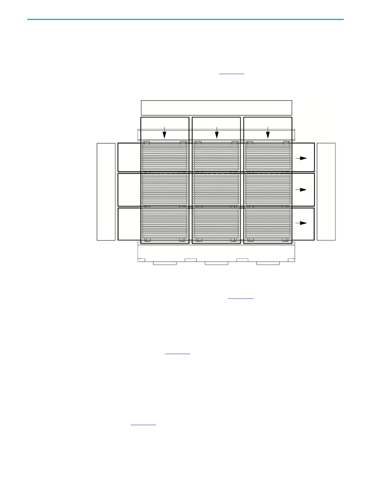
The isolation transformer’s three-phase primary coils are oriented A, B, and C
from left to right, as viewed from the front. The secondary windings are also
divided into three principal sections from top to bottom. The upper third are to
feed the power modules in the U output phase. The middle third are to feed the
power modules in the V output phase. The bottom third are to feed the power
modules in the W output phase (Figure 27
).
Figure 27 - Isolation Transformer Primary and Secondary Winding Orientation
The secondary windings are brought out to corresponding vertical isolated
stand-offs on the body of the transformer (orientated U, V, and W from left to
right as viewed from the front). See Figure 28
.
Each secondary winding set will have a designated U, V, and W terminal
connection. For example, (from top to bottom and left to right) the terminals
from the first winding set are 1W, 1V, and 1U, the terminals from the next
winding set are 2W, 2V, and 2U, and so on.
As shown in Figure 25
, the first winding set (1U, 1V, and 1W) will connect to the
three-phase input power connection of the first power module in the U motor
phase array (PCA1), the second winding set will connect to the second power
module in the U motor phase array (PCA2), and the third winding set will
connect to the third power module in the U motor phase array (PCA3). The next
three winding sets connect to the power modules in the V motor phase array.
The remaining three winding sets connect to the power modules in the W
motor phase array.
Figure 25
shows 3.0/3.3 kV configuration. The 6.0/6.6 kV and 10 kV
configuration have more power modules and therefore have more
corresponding isolation transformer secondary windings. The concept is the
same—the top third of the winding sets feeds the power modules in the U
PRIMARY WINDING INPUT
SECONDARY WINDING OUTPUT
A (L1) B (L2) C (L3)
U
V
W
SECONDARY WINDING OUTPUT
U
V
W
 Loading...


