Rockwell Automation Publication 6000-IN100A-EN-P - August 2020 23
Chapter 1 Drive Mechanical Installation
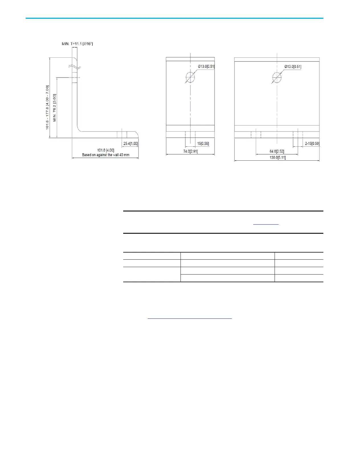
Figure 9 - ASTM A36 Angle Bracket Dimensions
Install Main Cooling Fans Main cooling fans are shipped in separate crates. The fans are shipped
assembled in the fan housing, but must be installed after siting the drive.
1. Place the fan housing on the top plate of the drive, making sure that the
socket is on the same side as the aviation plug.
2. Secure the fan housing using M6 hardware (six places).
See Torque Requirements
on page 59.
3. Connect the aviation plug located on top of the cabinet with the socket on
the fan housing.
Wall bracket BWall bracket A
IMPORTANT
See Mounting Clearance Distance in the PowerFlex 6000T Drives
Shipping and Handling Manual, publication 6000-PC100) to verify that the
fans have the appropriate clearance distance on top of the cabinet.
Table 2 - Fan Housing Specifications
Model Dimensions (HxWxD), approx. Weight, approx.
EC400 428 x 480 x 672 mm (16.9 x 18.9 x 26.5 in.) 30 kg (66 lb)
EC500
520 x 580 x 783 mm (20.5 x 22.8 x 30.8 in.) 45 kg (99 lb)
520 x 580 x 1125 mm (20.5 x 22.8 x 44.3 in.) 60 kg (132 lb)
 Loading...


