Rockwell Automation Publication 6000-IN100A-EN-P - August 2020 13
Chapter 1 Drive Mechanical Installation
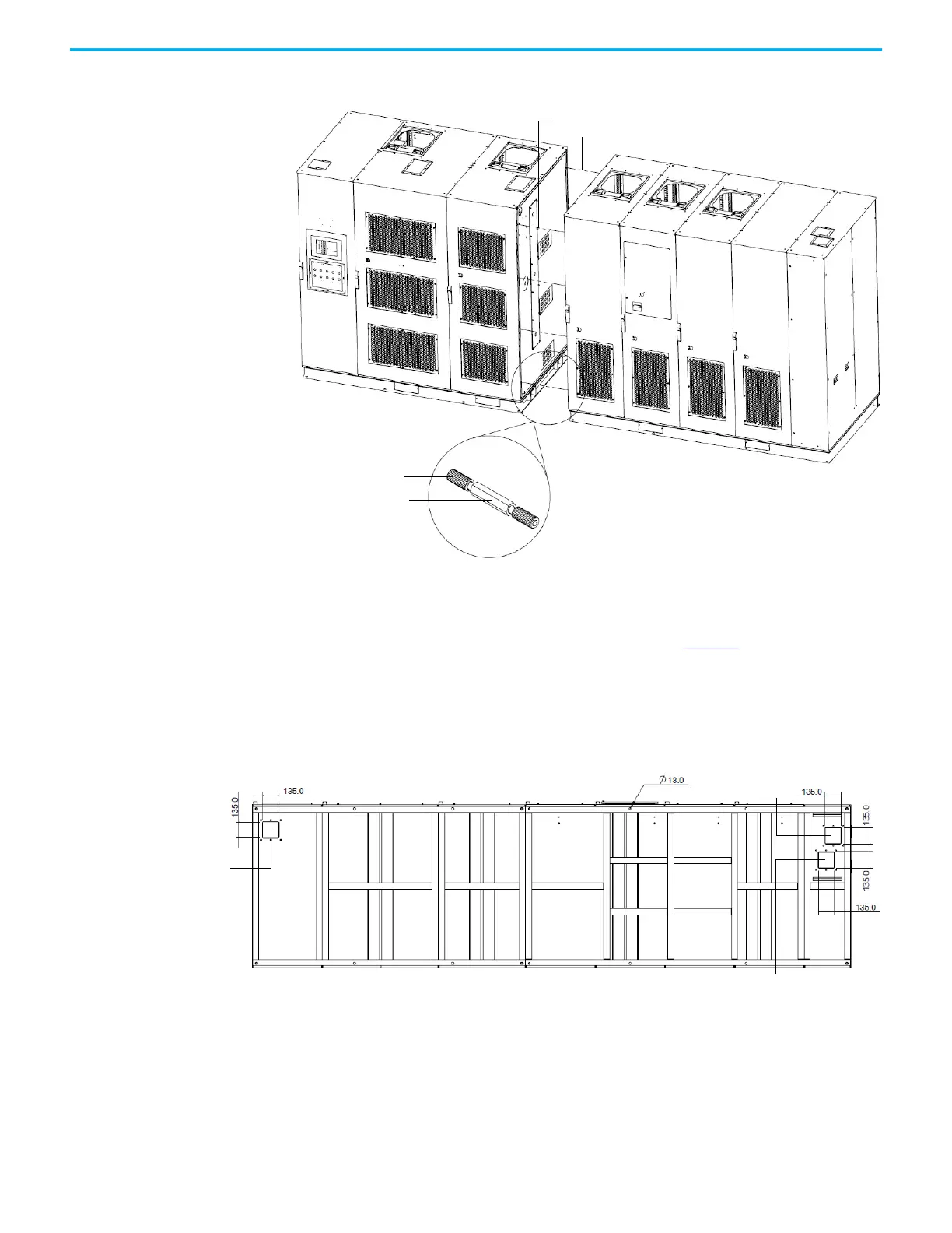
Figure 4 - Secure the Cabinets, B-Frame
Affix Cabinets to Floor Typical floor drawings show minimum clearance distance, conduit openings,
and mounting holes for anchor bolts, as shown in Figure 5
. See customer
specific dimensional drawing for outgoing motor and incoming line cable
openings.
Figure 5 - Typical Floor Drawing, B-Frame
Secure the cabinet to the channel steel base using M12 bolt (recommended),
lock washer, two flat washers, and a nut.
Secure with M6
hardware (8 places)
2-socket screw M6x16
Combination pillar
Isolation Transformer CabinetPower Module/LV Control Cabinet
Bottom View
Control signal
Output cable
Input cable
 Loading...


