12 Rockwell Automation Publication 6000-IN100A-EN-P - August 2020
Chapter 1 Drive Mechanical Installation
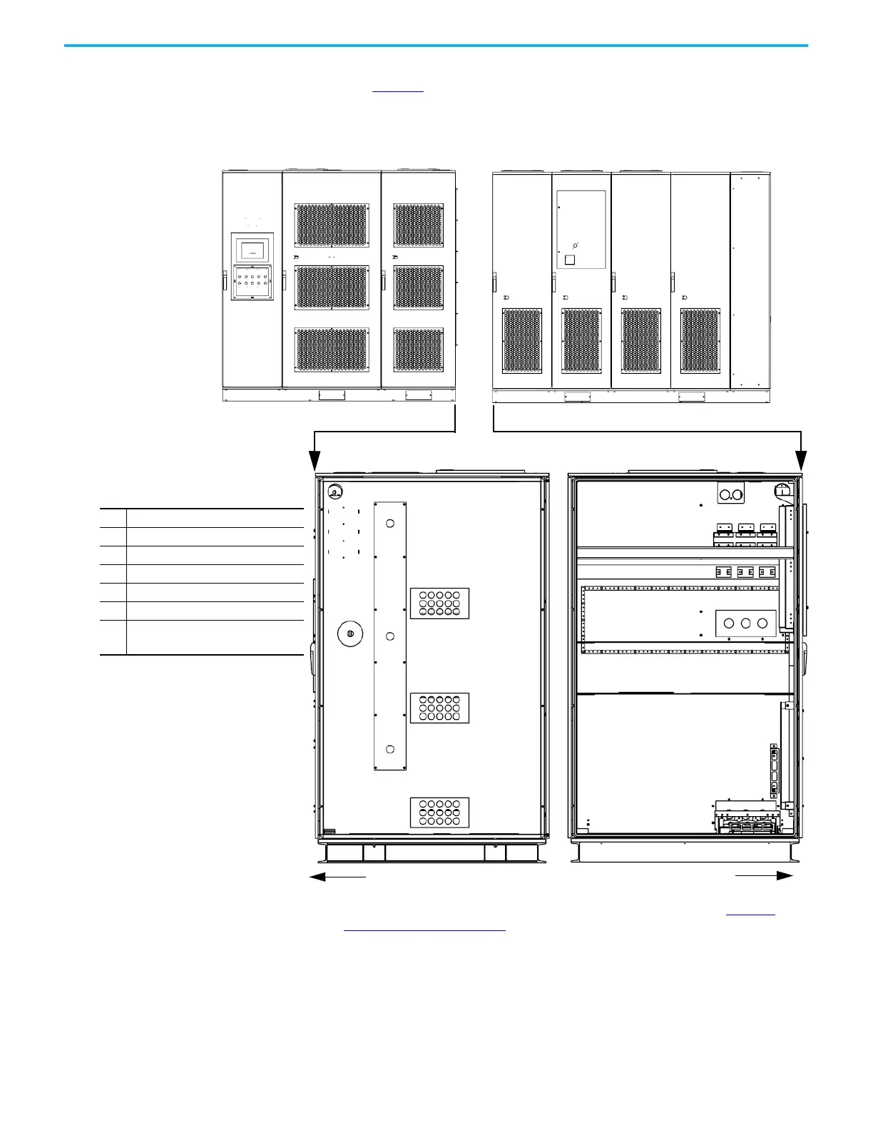
2. Align the cabinet side sheets together at the holes for the hardware
(see Figure 3
).
Figure 3 - Align the Cabinets, B-Frame (6 kV shown)
3. Secure the cabinets together using M6 or M8 hardware. See Torque
Requirements on page 59 for proper torque requirements.
Open the doors to access front edge joining holes (four or five places).
Isolation Transformer CabinetPower Module/LV Control Cabinet
Table 1 - Sidesheet Openings
❶
Front Wireway
❷
U Phase Motor Cable
❸
V Phase Motor Cable
❹
W Phase Motor Cable
❺
Ground Bus Connection
❻
Voltage Sensing Board Cables
❼
Isolation Transformer Secondary
Cables
(1)(2)
(1) The number of Isolation Transformer secondary
cables is dependent on motor voltage class.
• 9 cables per motor phase (27 total) for 3/3.3 kV
•12 cables per motor phase (36 total) for 4.16 kV
• 15 cables per motor phase (45 total) for 6 kV
•18 cables per motor phase (54 total) of 6.6 kV
•24 cables per motor phase (72 total) for 10 kV
• 27 cables per motor phase (81 total) for 11 kV
(2) 6/6.6 kV configurations only require 18 cable
hole locations per phase. Extra cable hole
locations allow for added installation flexibility.
❶
❸
❹
❺
❻
❷
Front
Front
❼
Side View
❼
❼
 Loading...


