52 Rockwell Automation Publication 6000-IN100A-EN-P - August 2020
Chapter 3 Drive Electrical Interconnection
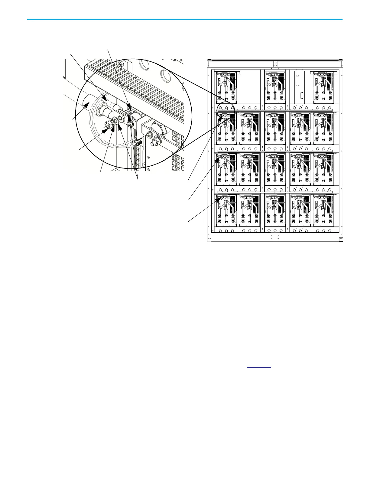
Figure 30 - 6.6/6.9 kV Power Module Configuration – B-Frame
Connect LV Control and Fan
Wiring Bundles
There are control wiring bundles that must be reconnected after the drive
cabinets are connected together. These control wiring bundles are connected
for the factory test and then disconnected and bundled at the shipping splits
before shipment.
For exact wire numbers and terminal block designations, see the Electrical
Drawings.
Connect Ground Bus A solid ground bus is located at the bottom front of each cabinet. When a
shipping split is required, ground bus connectors are supplied. One is attached
above the solid ground bus and one below (Figure 31
).
Ground bus connection openings are provided in the cabinet sidesheets for
this connection.
Hex nut
Flat washer
Lock washer
Hex bolt
Motor cable
VSB cable
U Phase
V Phase
W Phase
Front View
 Loading...


