Rockwell Automation Publication 6000-IN100A-EN-P - August 2020 63
Appendix D
Power Cabling and Control Signal Wiring Details
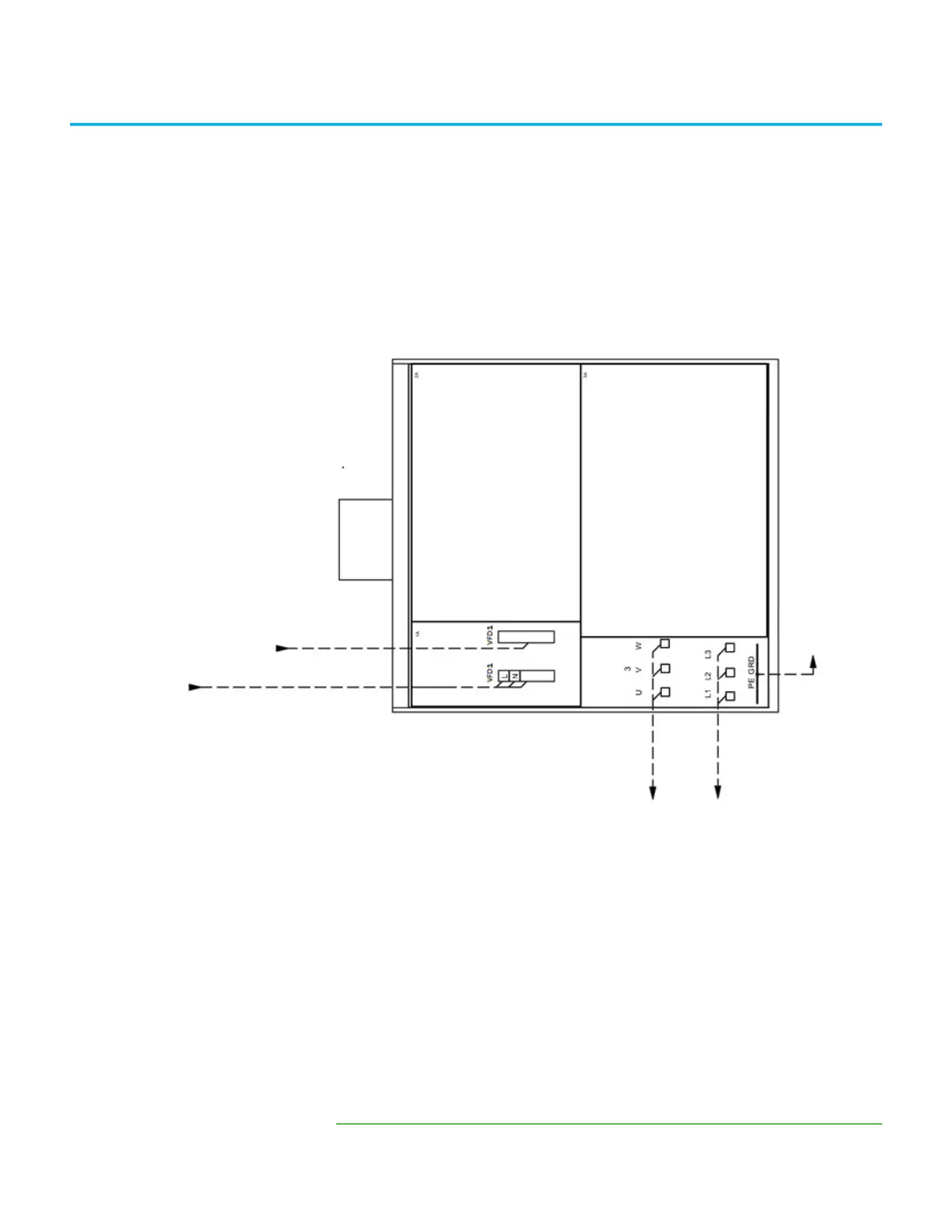
Schematic Diagrams Figure 32 - Schematic Diagram of the Drive System without a Bypass Cabinet, A-Frame
(a)
(a) Wiring locations are for design reference only; actual wiring must comply with the drawings
that are provided with the drive.
DANGER:
The medium voltage drive is one component in this system, which includes an input device that is supplied by others.
The supplier of the input device is responsible for confirming that there is safe access to the input/output drive (if used) and safe access to the drive.
MFN1
Customer Supplied
Ground
4.16 kV, 3 phase, 60 Hz
Upstream Circuit Breaker
(Customer scope of supply)
To Motor
Control Signal
110/120/220/230/240V AC, 1 phase, 50/60 Hz.
Control Signal with Branch Circuit Protection
(Minimum 3 kVA Capacity is needed)
 Loading...


