44 Rockwell Automation Publication 6000-IN100A-EN-P - August 2020
Chapter 2 Drive Electrical Installation
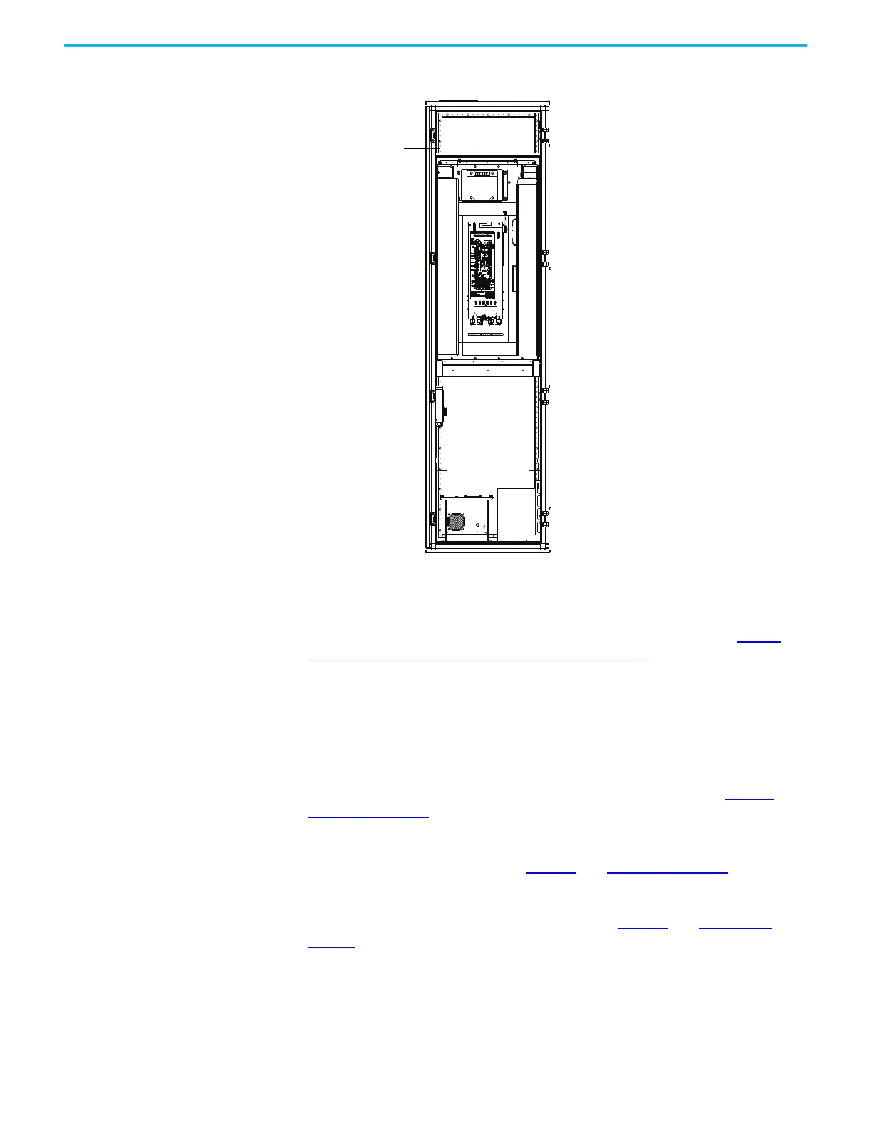
Figure 23 - Terminal Block Strip locations
Connect External Control
Signal Wiring
This section summarizes the control signal wiring from the remote DCS/PLC
or discrete control to the drive. General connections are detailed in Power
Cabling and Control Signal Wiring Details on page 63. Refer to the Electrical
Drawings for connection information specific See the drive being installed.
Analog and Digital I/O Overview
Four 4…20 mA analog input signals. One may be used for DCS with rotating
speed setting and three for backup. For detailed information, see Table 14
and
Table 15 on page 66
.
Up to four 4…20 mA analog output signals for indication signals such as output
motor current and frequency. See Table 14
and Table 15 on page 66.
Twelve passive dry contact inputs (internal 24V DC power supply) start/stop
and reset controls. For detailed information, see Table 14
and Table 15 on
page 66. These inputs are scalable depending on user requirements.
Four dry contact outputs from the POD option cards are standard with a
capacity of 20W for indication. Interposing relays are provided to interfacing
to power switching devices and fault status information. The quantity is based
on the options ordered with the drive. The rating of these contacts are
-A-
VFD1 Terminal
Block strip
 Loading...


