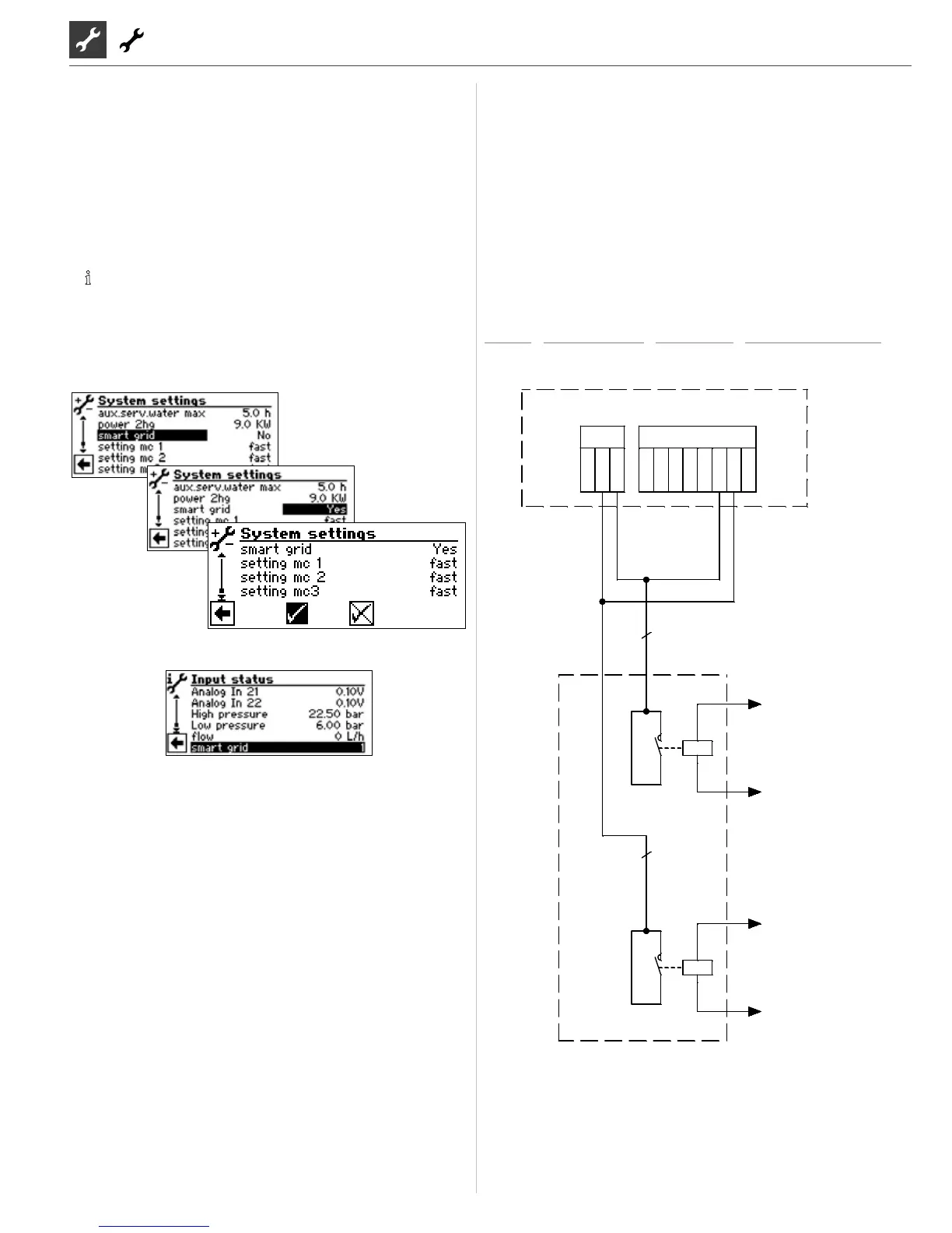
SMART GRID
Use of the Smart Grid option depends on the unit type and soft-
ware version.
If you have any questions regarding the availability of the Smart
Grid functionality in your electricity tari, please contact your
electricity supply company
The function is connected via two contacts of the utility lock,
from which four possible operating states result.
.
NOTICE
If utility lock is applied, the Smart Grid functional may not
be activated.
ADJUSTABLE UNDER SYSTEM SETTINGS:
Current operating state visible under Information->Inputs
Operating state 1 (1:0)
Corresponds to the current utility lock.
Operating state 2 (0:0) - deviation from standard control behavi-
our:
The heat pump operates exclusively within the range of the set-
point hysteresis (i.e. below the setpoint).
Heating: If the system temperature drops to below the lower hy-
steresis, the heat pump is switched on and heats the system up to
the setpoint. The upper hysteresis is ignored. The heat pump on-
ly heats until there is no longer any need to worry about possi-
ble comfort losses. Domestic water heating takes place as normal.
Operating state 3 (0:1) - corresponds to standard control behavi-
our:
The target temperature is the set setpoint temperature for hea-
ting and domestic hot water. These set temperatures are held ta-
king into account the respective hystereses.
Operating state 4 (1:1) - deviation from standard control behavi-
our:
The heat pump operates exclusively within the range of the set-
point + hysteresis (i.e. above the setpoint).
Heating: If the system temperature drops to the setpoint, the he-
at pump is switched on and heats the system up to the setpoint +
hysteresis points
DHW: The controller generates a positive hysteresis whose magni-
tude is equal to the lower hysteresis and regulates in this area (set
temperature + upper hysteresis).
TERMINAL DIAGRAM
SW H3
•
SWCV H1/H3
•
WZSV H3
•
PWZSV H1/H2/H3
 Loading...