HOT WATER SENSOR
The domestic hot water sensor is an optional accessory and only
functionally-relevant for a separate domestic hot water tank. You
may only use domestic hot water sensors which have been appro-
ved by the manufacturer of the heat pump..
ATTENTION
The domestic hot water tank must be lled before connec-
ting the domestic hot water sensor to the heating and heat
pump regulator.
If not already prepared at the factory, mount the domestic hot
water sensor (Ø = 6 mm) on the halfway level of the domestic hot
water tank – and always above the internal heat exchanger of the
domestic hot water tank.
1 Hot-water tank
2 Domestic hot water sensor (Ø = 6 mm)
3 Heat exchanger
4 Cold water connection
5 Domestic hot water connection
EXTERNAL RETURN FLOW SENSOR
The return ow sensor (optional accessory) is functionally-rele-
vant for hydraulic integration of an isolating tank (multifunction
tank .). This has to be installed as follows:
ZUP
TRLext
HUP
1 Separation or multi-functional storage tank
2 Circulation pump in the separation
storage tank (heat pump circuit)
3 Circulation pump from the separation
storage tank (heating circuit)
4 External return sensor (Ø = 6 mm)
ZUP Charging loop, heat pump
HUP Discharging loop, heating circuit
Connect the return ow sensor coming from the isolating tank to
the circuit board of the heating and heat pump regulator.
ASSEMBLY AND INSTALLATION OF SENSORS
The external sensor is a function-critical accessory and included
in the scope of supply.
NOTICE
If the external sensor is not installed or defective, the hea-
ting and heat pump regulator automatically sets the exter-
nal temperature to -5 °C. The status display of the opera-
ting element lights up red, the screen of the operating ele-
ment reports a fault.
ATTENTION
Mount the external sensor on the north or northeast side
of buildings. The sensor must not be exposed to direct
sunlight.
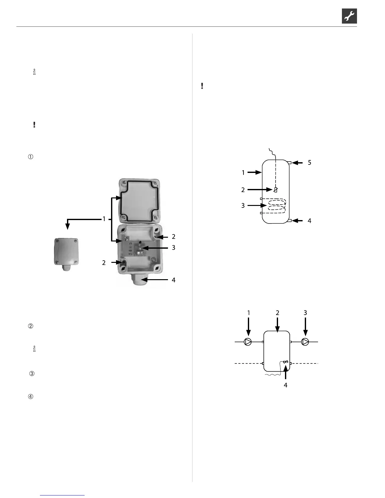
Open the housing of the external sensor and align ≥ 2 m over
the base of the fastening point. The cable gland must point
to the base.
1 xternal sensor housing
2 Fastening holes
3 Cable gland
4 External sensor
Pencil on fastening holes and drill, insert dowels and screw
housing of the external sensor onto the wal.
NOTICE
Dowels and screws for fastening the external sensor are
not included in the scope of supply.
Loosen cable gland from the housing of the external sensor,
lead the 2-wire cable (Ø ≤ 1.5 mm² per wire, cable length ≤ 50
m) through the cable gland into the housing.
Clamp on cable, tighten cable gland and close the housing of
the external sensor.

 Loading...