CONTROL UNIT VARIANTS
Depending on the heat pump type, the control unit integrated in
the heating and heat pump controller is equipped with the fol-
lowing interfaces:
TYPE 1
N Network
S Connection to the control board
TYPE 2
N Netwoerk
L LIN-BUS
S Connection to the control board
TYPE 3
R RS485 for connecting the
room control unit (RBE)
N Network
L LIN-BUS to the control board
S not assigned, LWV, LWCV, LWAV Mod-Bus
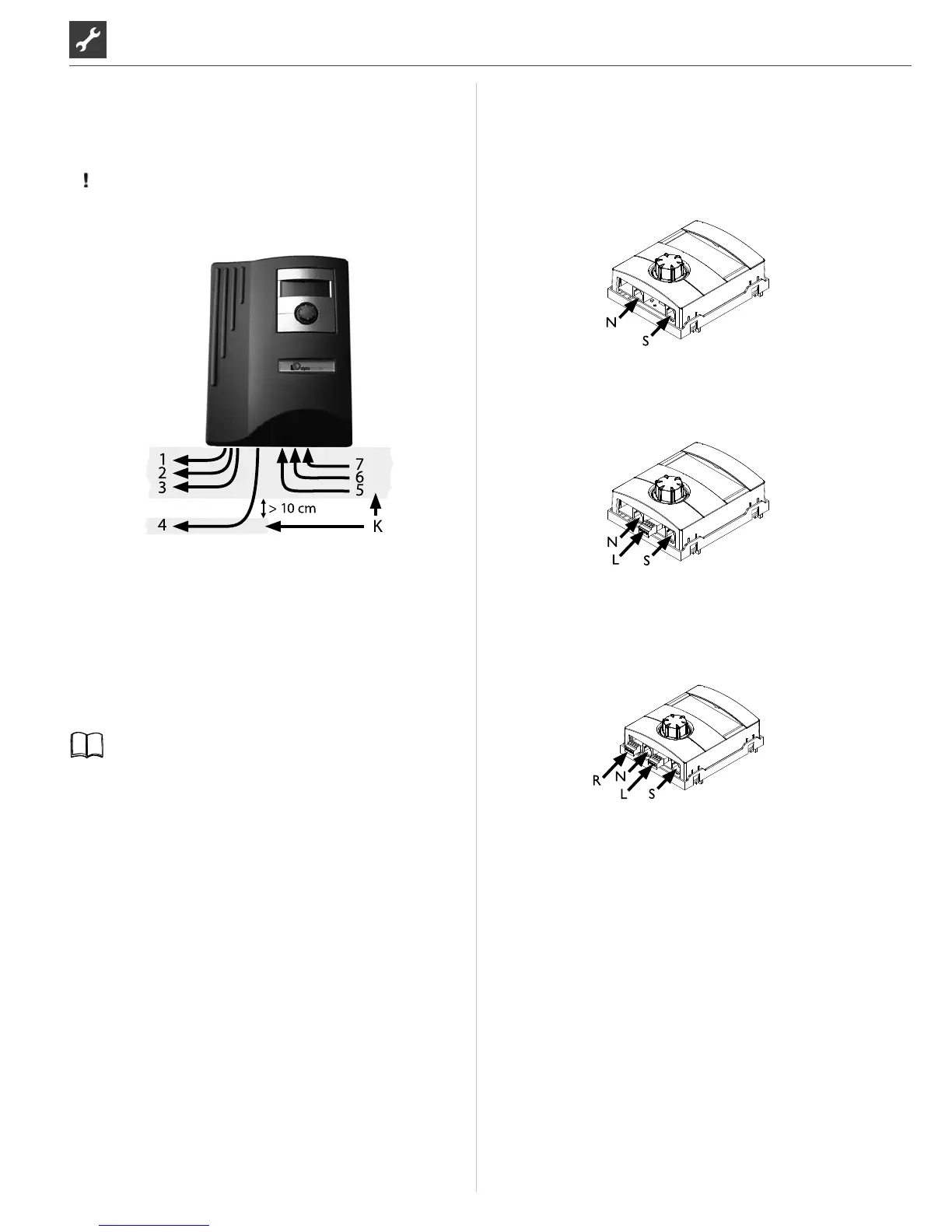
Route all lines that you connect to the heating and heat
pump control outside the heating and heat pump in a
cable duct (necessary for strain relief; to be realised at the
customer).
ATTENTION
The BUS communication cable must be laid at a spacing >
10 cm from other cables. Therefore, lay with the appropri-
ate spacing in a separate cable duct.
1 230 V power supply to the outdoor unit
2 PWM control signal for circulation pump
3 other 230 V outputs (circulation pumps, mixers, etc.)
4 BUS communication cable to the outdoor unit
5 Sensor cables including the TRL return sensor
on the return to the heat pump
6 other 230 V inputs (electricity outage etc.)
7 1~/N/PE/230V power supply (to the terminal block);
cable cross-section max. 2.5 mm², internal fuse 6.3 AT
K Cable ducts
Installation instructions for this in the operating instruc-
tions of your heat pump.

 Loading...