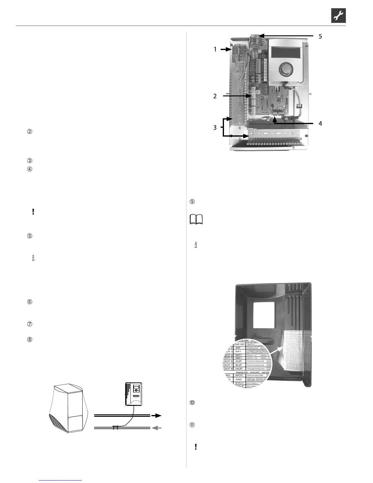
1 Connected 1~/N/PE/230 V power supply for
wall-mounted controller and outdoor unit
2 Connected TRL return sensor (on NTC8)
3 Laying cables in the cable ducts
4 Connected BUS communication cable
5 Connected PWM control signal for circulation pump
If necessary, install additional external cables.
Instruction manual for your appliance, “Connection
layout” and “Circuit diagrams” for your appliance type
NOTICE
The inputs and outputs on the control board are assigned
as shown on the device’s terminal connection diagram.
In addition, the assignment is shown on the inside of the
housing of the wall-mounted controller.
Place covers on the cable ducts. Swivel folding bracket of the
cable entry back into the initial position and allow to latch into
place below the fastening screw. Tighten fastening screw.
Put the housing cover back on and tighten the side fastening
screws..
ATTENTION
1 Terminal block for 1~/N/PE/230 V voltage supply
2 EVU bridges (must be removed when
connecting a oating contact)
3 TRL return sensor terminal (on NTC8)
4 Cable ducts with covers (covers now
shown here in the gure)
5 Cable entry with folding bracket
6 Fastening screw of the folding bracket
7 Terminal (X10 Modbus) for BUS cable to the outdoor unit
8 Slot for optional “2.1-EP” circuit board
9 LIN-BUS communication cable between control
board and control unit (wired in the factory)
10 Control card of the heating and heat pump control
11 Operating element
12 Connection for circulation pump PWM control signal
Loosen fastening screw of the folding bracket for the cable
entry and pull the folding bracket downwards until it is pos-
sible to fold away upwards. Fold folding bracket upwards and
away to the side .
Remove covers from the cable ducts.
Connect the BUS communication cable, which leads to the he-
at pump, to terminal X10 of the controller board.
Then route the BUS communication cable downwards and
through the cable ducts and through the cable entry to the
outside.
ATTENTION
The BUS communication cable and power cables must be
laid with a spacing > 10 cm between them.
Connect the 230 V voltage supply line to the voltage supply
terminal block.
NOTICE
Internal fuse 6.3AT.
The terminal block has spring-type terminals to maximum
2.5 mm2.
Insulate the cable jacket so that the jacket end is located
between the sealing lip and cable duct..
Connect the 230V power supply for the outdoor unit to the
terminal block and route it downwards through the cable
ducts and through the cable entry to the outdoor unit outside.
Connect the PWM control signal for the circulation pump to
the terminal block --X10.
A separately packed return sensor (TRL) with appropriate in-
stallation materials is enclosed with the air/water heat pump
for outdoor installation. Use cable ties and heat transfer com-
pound to x the return sensor to the return (heat-conducting
pipe) to the heat pump as shown in the gure and connect (to
NTC8) as shown in the circuit diagram.
Basic wirng:

 Loading...