Chapter II Installation and Wiring
16
Table 2-1 Function and Description of Main Circuit Terminal
Terminal Name and Function Description
Main circuit power supply input terminal:
The drive shall be connected to three-phase 220V or three-phase
380V or single-phase 220V power supply according to different
models; as for single-phase input, it can only be connected to L1
and L2 terminals, and L3 shall not be wired; the drive of some
model are applicable to three-phase 220V and single-phase 220V
power supplies, and the single-phase power supply should be
connected to L1 and L3 terminals. Refer to the nameplate of the
drive for detailed information about the power supply specification.
Control power supply input terminal:
220V series drive: AC 220V (+/-15%), 50/60HZ
380V series drive: AC 380V (-15%~+10%), 50/60HZ
External braking resistor connecting terminal:
If a built-in braking resistor is used, B2 and + are in short
connection;
If an external braking resistor is used, the external braking resistor
is connected to B1 and + end, and the jumper between B2 and +
shall be removed.
Three-phase AC output terminal: connected with U, V and W of
the servo motor
Grounding terminal: connected with the power supply grounding
terminal and the motor grounding terminal
Notes: the figure shows the terminal arrangement for 220V5.5A drive; the terminal
arrangement for drives of other specifications may be different from this; the actually
marked terminal code shall prevail.
Wiring Steps for Spring Type Main Circuit Terminal:
Take the spring type main circuit terminal from the servo drive.
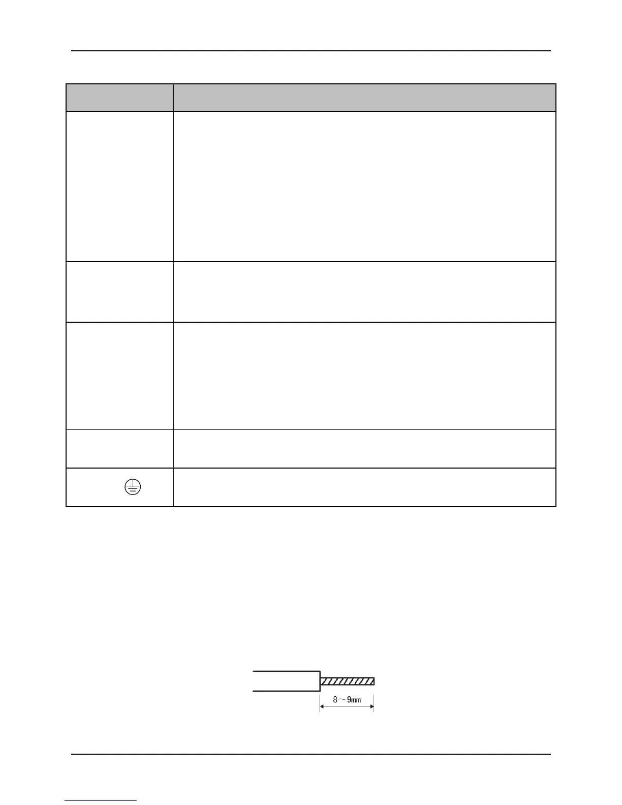
Strip the insulating layer of the wire to be connected as shown in the figure.


 To Next Page