Chapter II Installation and Wiring
31
2.9 Interface Circuit Principle
The I/O signal of the servo drive and the interface circuit connection of the host device
are as shown in Fig. 2-10 to Fig. 2-17:
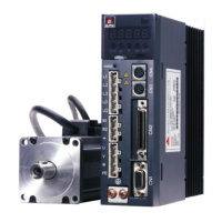
Analog Input Circuit
The I/O interface CN2 of the drive has one loop of analog input (0~±10V), as the speed
command or torque command signals; the signal specification is as follows:
The maximum allowable voltage is ±15V and the input impedance is approximately
30kΩ.
Fig. 2-10 Analog Input Circuit
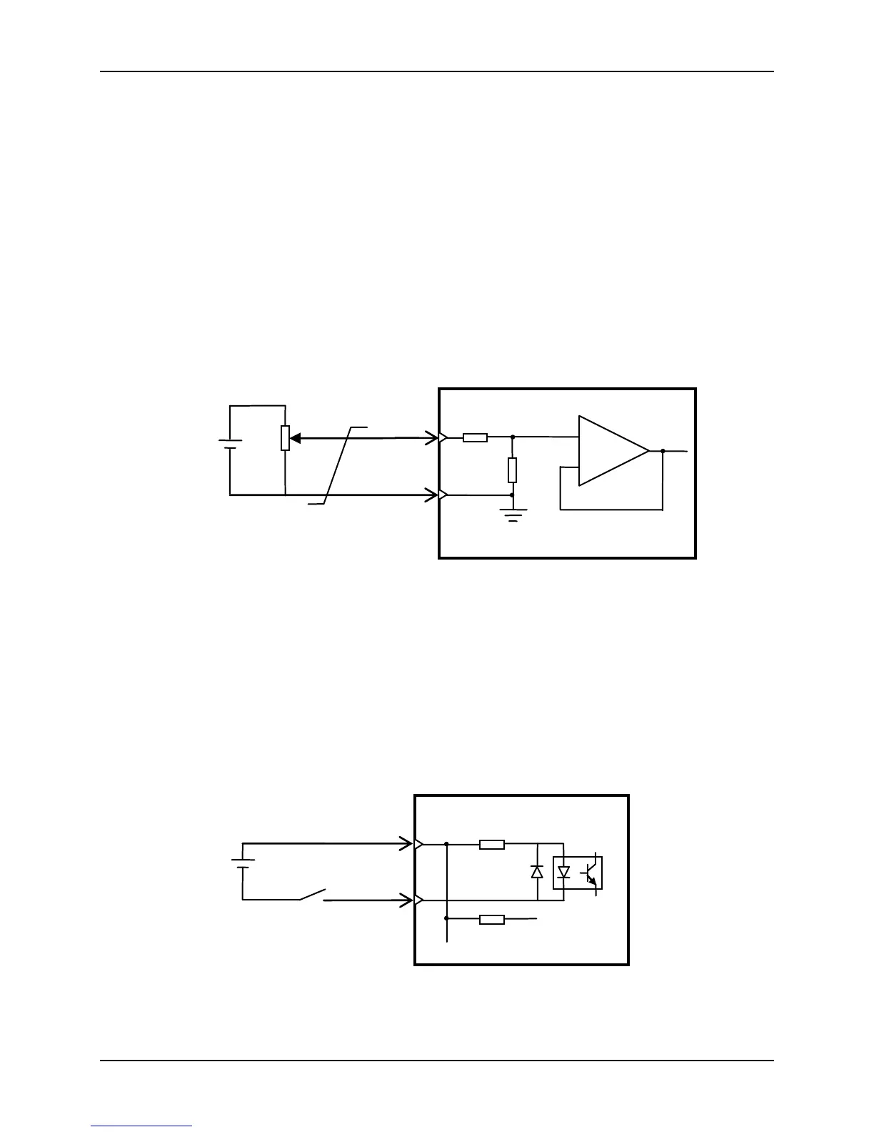
Digital Input Circuit
If the host device is relay output:
Fig. 2-11 Digital Input Circuit (a)
 Loading...