Chapter III Display & Operation
40
Chapter III Display and Operation
1. Close the input power supply upon completion of the
terminal cover installation; please do not remove the terminal
cover when the power is on to avoid electric shocks.
2. Please keep off the mechanical equipment to avoid personal
injury possibly caused by the sudden start-up of the servo
drive when electrified.
1. Please do not touch the brake resistor, if any, to avoid any
electric shock or burning for it may be of high temperature
because of election.
2. Please check the application range of the motor and
machinery before operation to avoid personal injury.
3. Please check the signal during operation to avoid
equipment damage and electric shock.
3.1 Introduction to Operation and Display Interface
The keyboard is constituted with a 5-bit 7-segment LED display and 5 operation keys.
It enables the user to perform function setting, parameter setting, state display, etc.
3.1.1 Key Functions
There are 5 keys on the servo drive keyboard, each with function indicated in Table
3-1.
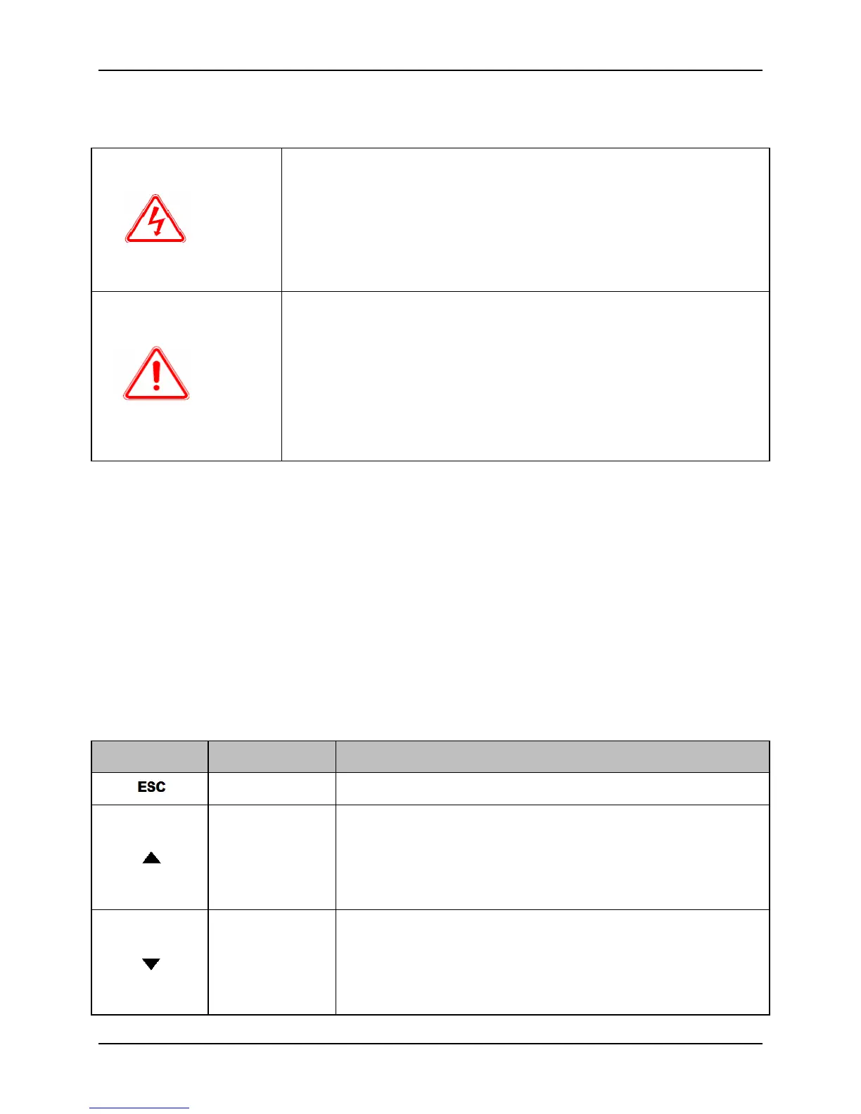
Table 3-1 Key Functions
Return to the previous menu
Increasing the set value; constant pressing for rapid
increase of the set value
Speeding up during speed trial operation
Forwarding in JOG mode
Degreasing the set value; constant pressing for rapid
decrease of the set value
Speeding down during speed trial operation
Reversal in JOG mode
 Loading...