EasyManua.ls Logo

Alpha AS100 Series - Basic Parameter Adjustment; The Setting of Electronic Gear Ratio

Alpha AS100 Series
179 pages
Print Icon
To Next Page IconTo Next Page
To Previous Page IconTo Previous Page
Loading...
Chapter IV Operation
58
P04。00
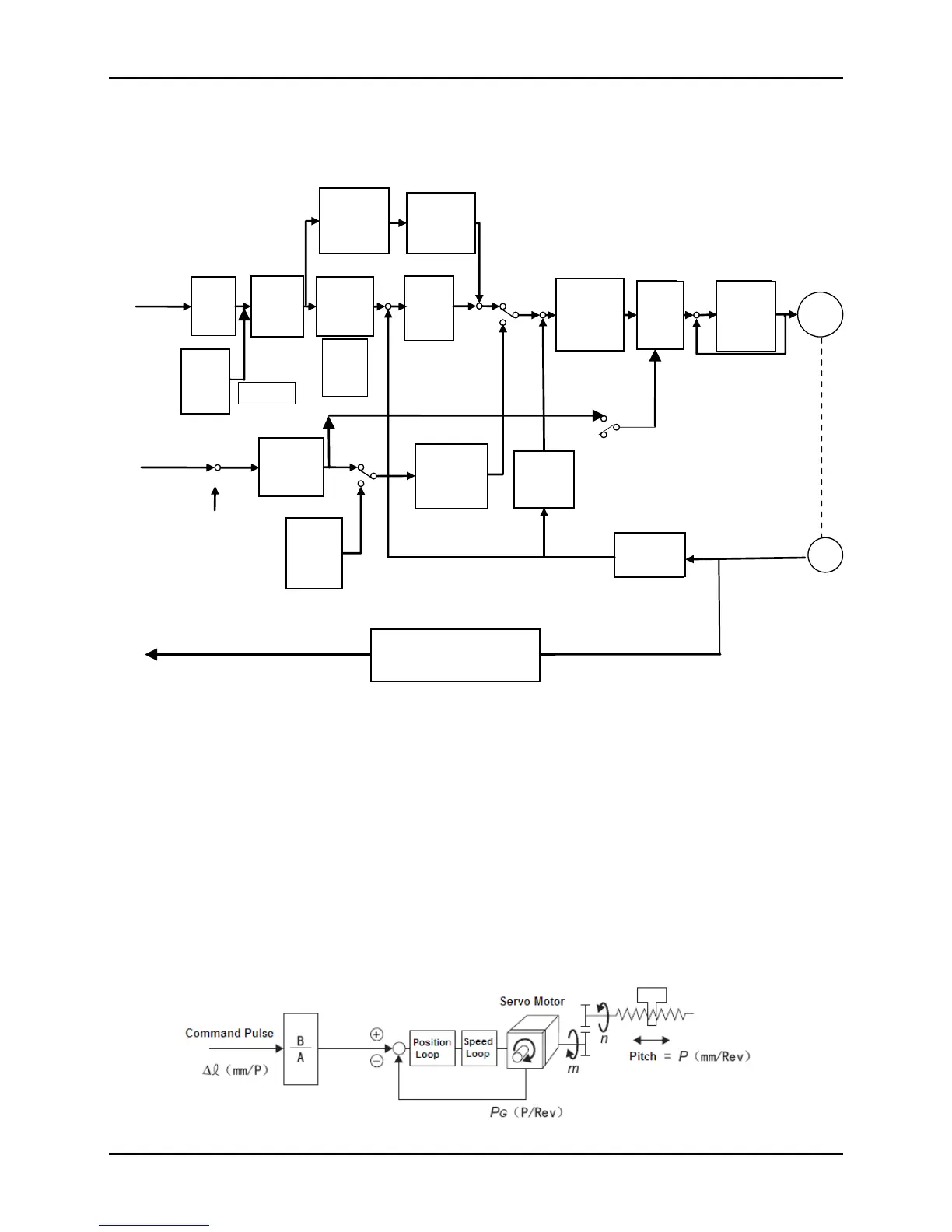
4.3.2 Basic Parameter Adjustment
Fig. 4-5 The Diagram of Basic Parameter Adjustment
Note: optimization adjustment of torque loop parameters have been done before
ex-factory, so the users do not need to adjust torque loop gain P09.07 and torque loop
integral time constant P09.08.
4.3.3 The Setting of Electronic Gear Ratio
Electronic gear ratio (G=B/A) calculation formula:
Instruction
smooth
filtering
Pulse
input
mode
Electroni
c gear
ratio
Position
loop gain
Simulation
instruction
gain
Speed
instruction
low-pass
filter
Feed-forwar
d low-pass
filter
Speed loop
gain integral
time
constant
Torque
instruc-
tion
filter
Torque
loop gain
integral
time
constant
Velocity
calculation
Internal
multistage
speed
Fourfold
frequency
P00.05
P04.04
P04.05
-
-
-
-
P00.04
P04.01
P00.07
P00.03
P00.02
P00.08
P00.09
P09.07
P09.08
P03.13
P00.11
P00.02
Zero compensation
P03.12
Analolg
instruction
Position
instruction
PMSM
P00.12
Motor
Encode pulse frequency
division ratio
Encoder frequency pulse output
P01.05
P01.06
Encoder
PG
P00.02
P11.xx
P00.10
Moving
average
filtering
P04.08
Internal
multistage
position
P10.xx
Position instruction source
Speed
feed-forward
gain

Table of Contents