EasyManua.ls Logo

Alpha AS100 Series - Page 50

Alpha AS100 Series
179 pages
Print Icon
To Next Page IconTo Next Page
To Previous Page IconTo Previous Page
Loading...
Chapter IV Operation
49
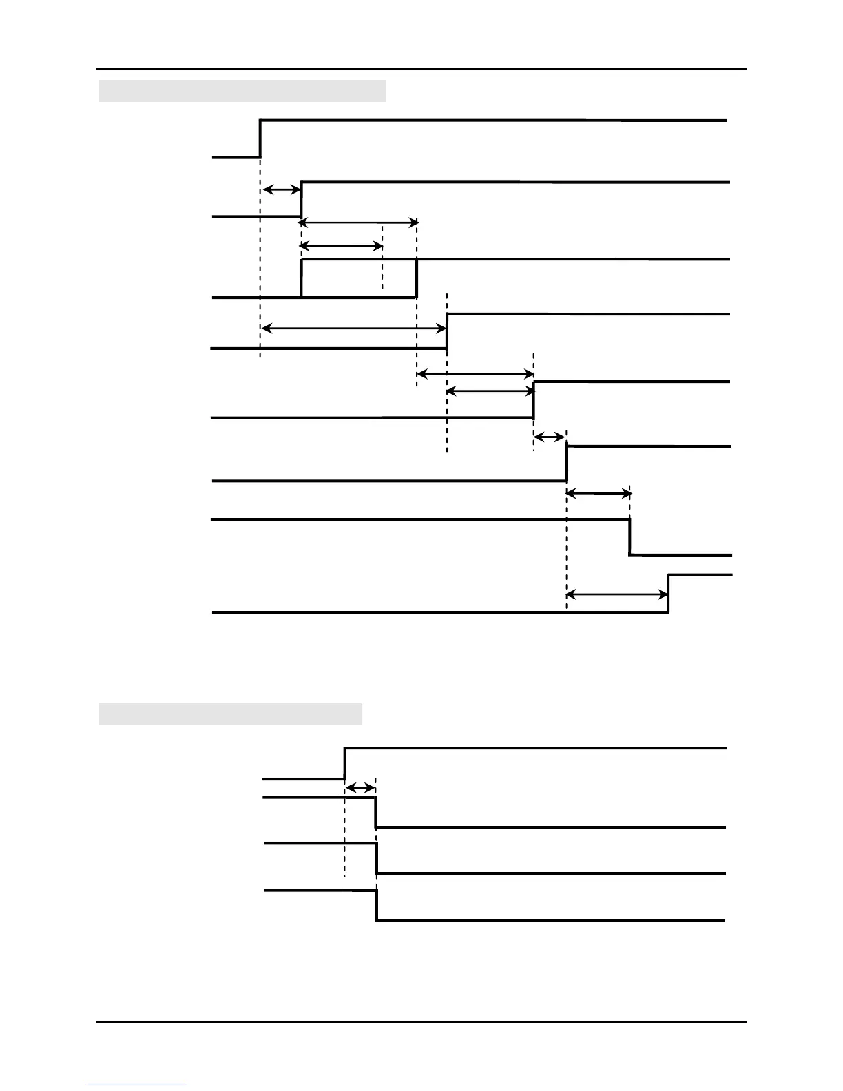
·The Sequence Diagram of Power on
Fig. 4-2 The Sequence Diagram of Power on
·The Sequence Diagram of Alarm
Fig. 4-3 The Sequence Diagram of Alarm
Normal
Abnormal
Connected
to power
0.5~5ms
Disconnected to power
Output Tr OFF
Output Tr ON
Servo alarm output
(ALM)
Servo enable output
(S-RDY)
Motor is connected
to power
Abnormality or not
Output Tr OFF
Output Tr ON
Connected to power
OFF
ON
OFF
About 1.0~4.0s
Confirm
About 2s
About 1.5s
Initialization
Reset
Usual work
Above 0s
ON
OFF
Above 10ms
Output Tr OFF
Input coupler OFF
Above 0s
Output Tr ON
Input coupler ON
Disconnected to power
About 60ms
Above 100ms
Position, speed and torque
instruction
No instruction
Above 10ms
Servo enable input
(S-ON)
Servo enable output
(S-RDY)
Motor is connected to
power
Main Power
(L1, L2, L3)
The Microprocessor
action
Internal Control of Power
Control of Power
(LC1, LC2)
Instruction

Table of Contents