Do you have a question about the Alpha CXPS-C and is the answer not in the manual?
Explains symbols used in the manual for safety information.
Provides essential warnings before installing the enclosure and components.
Details hazardous voltages and precautions for electrical work.
Outlines safety procedures for handling and installing batteries.
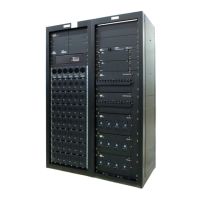
Describes the CXPS-C power system's purpose and components.
Information on system features and ordering options.
Details the Cordex HP System Controller, Rectifier Shelves, AC Termination, and Standalone options.
Details rectifier modules, including hot-swappable capability and alarms/LEDs.
Describes distribution bays, tiers, shunts, LVLD, LVBD, alarms, and buses.
Details inter-bay busbars, bay expansion, and return bar options.
Provides centralized setup, control, and monitoring via controller and its features.
Describes L-ADIO, 61-ADIO, RIPM, and Shelf/Bay ID peripherals.
Guidelines for selecting a suitable location for the power system and batteries.
Lists components not supplied with the system for installation.
Lists essential tools and test equipment for DC power system installation.
Information regarding concrete floor requirements and seismic considerations.
Details Alpha's commitment to sustainable packaging materials.
Procedures for inspecting product for damage upon receipt.
Verifying shipment contents and contacting support.
Details floor drilling procedures for seismic and non-seismic installations.
Steps for positioning and securing the bays to the floor.
Instructions for bolting adjacent bays together.
Describes the installation of inter-bay DC bus work kits.
Applies to new and expansion installations for shunt and signal cables.
Details the installation of the expandable external return bar kit.
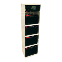
Provides guidelines for battery installation, including prep, external install, and probes.
Provides a template for typical VRLA battery maintenance.
Covers installer responsibilities, wire sizing, and torque values.
Details methods for connecting frames and reference grounds to the system.
Details AC supply specifications, input options, and wiring the distribution panel.
Covers distribution wiring topics like breaker alarms, battery return, DC cables, and external alarms.
Instructions for installing a standalone power bay.
Instructions for installing a standalone distribution bay.
Verifies connections before powering up the system.
Steps to verify AC input and power the rectifier shelf.
Verifies battery polarity and connects batteries.
Final system parameter configuration and alarm testing.
Details setting Bay IDs sequentially on Shelf ID boards.
Overview of system testing and calibration methodologies.
Procedures for initial battery charging and discharge testing.
Completing necessary documentation like reports and wiring lists.
Recommends replacing MOV surge suppressors every five years.
Recommends checks every six months for battery parameters.
Procedures for replacing the controller's lithium battery.
| Brand | Alpha |
|---|---|
| Model | CXPS-C |
| Category | Power Supply |
| Language | English |