26 Altera Corporation
Board Components Nios Development Board Reference Manual, Cyclone Edition
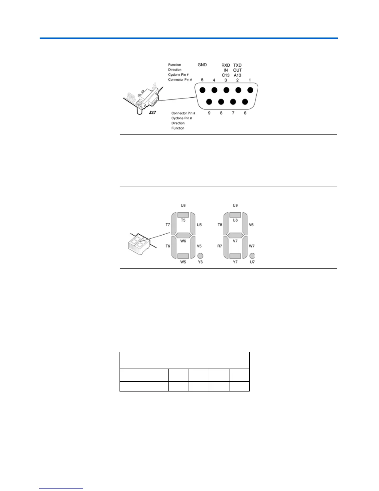
Figure 15. Debug Serial Port Connector – J27
Dual
7-Segment
Display
U8 and U9 are connected to the Cyclone device so that each segment is
individually controlled by a general-purpose I/O pin. When the Cyclone
pin drives logic 0, the corresponding LED turns on. See Figure 16 for
Cyclone device pin out details.
Figure 16. Dual-7-Segment Display
The pre-loaded Nios reference design includes parallel input/output
(PIO) registers and logic for driving this display.
Push-Button
Switches
SW0 – SW3 are momentary-contact push-button switches that provide
stimulus to designs in the Cyclone device. See Figure 17 on page 27. Each
switch is connected to an Cyclone general-purpose I/O pin with a pull-up
resistor as shown in Table 7. The Cyclone device pin will see a logic 0
when each switch is pressed.
Table 7. Push Button Switches Pin Out Table
Button
SW0 SW1 SW2 SW3
Cyclone Pin W3 Y4 V4 W4