Altera Corporation 33
Nios Development Board Reference Manual, Cyclone Edition Board Components
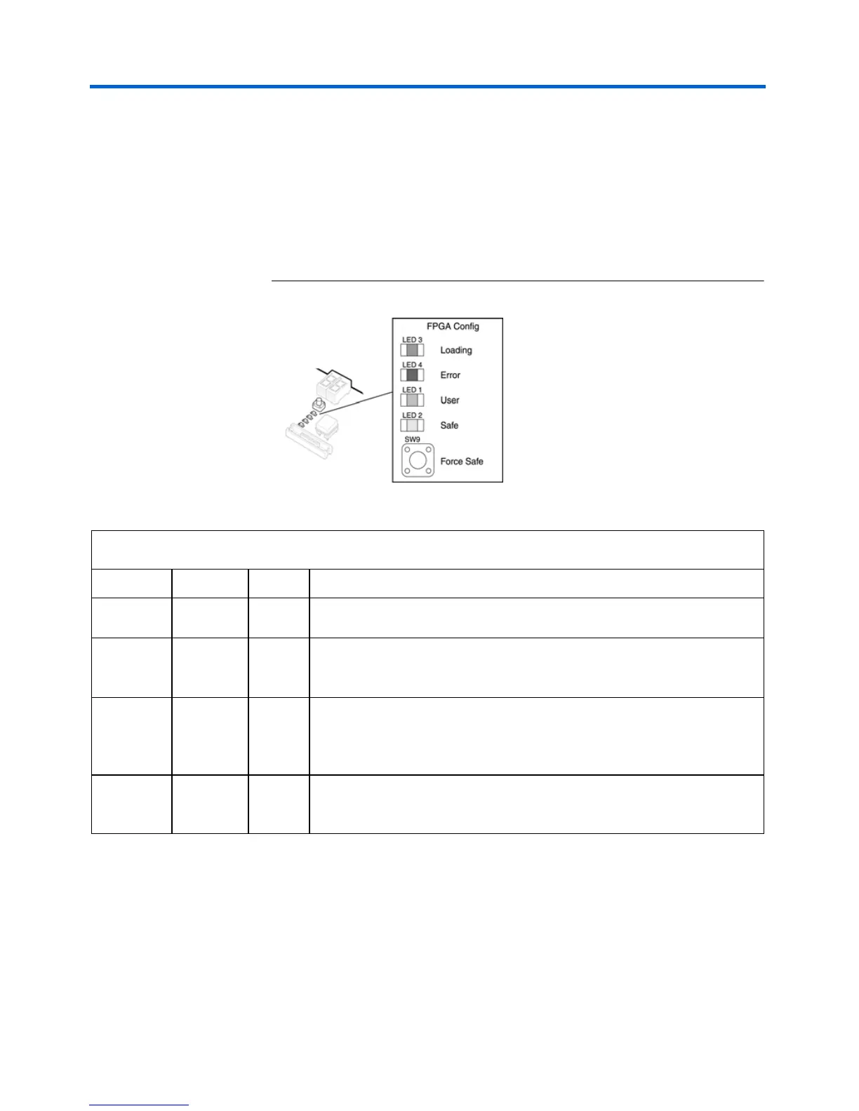
The Configuration-Status LEDs
The MAX device is connected to four status LEDs that show the
configuration status of the board at a glance (see Figure 18). The user can
tell which configuration, if any, was loaded into the board at power-on by
looking at the LEDs (see Table 11 on page 33). If a new configuration was
downloaded into the Cyclone device via JTAG, then all of the LEDs will
turn off.
Figure 18. LED1 – LED4
Configuration and Reset Buttons
The Nios development board uses dedicated switches SW8, SW9 and
SW10 for the following fixed functions:
Table 11. Configuration Status LED Indicators
LED LED Name Color Description
LED3 Loading Green This LED blinks while the MAX configuration-controller is actively
transferring data from flash memory into the Cyclone FPGA.
LED4 Error Red If the red Error LED is on, then configuration was NOT transferred from
flash memory into the Cyclone device. This can happen if, for example, the
flash memory contains neither a valid user or safe configuration.
LED1 User Green If the Cyclone device was successfully configured with data from the
EPCS4, LED1 will blink slowly. If the Cyclone device was successfully
loaded with the user configuration from flash memory, LED1 will remain on
continuously.
LED2 Force Safe Amber This LED turns on when the safe configuration is being transferred from
flash memory and stays illuminated if the safe configuration was
successfully loaded into the Cyclone device.