BOOM BARRIER BV586888
ASSEMBLY
If you have aready foundation to install the barrier, then mark and drill four holes at the barrier
installation site (Fig. 12), install the anchor bolts (not included in the scope of delivery). Install
the barrier cabinet (Fig. 10, 11).
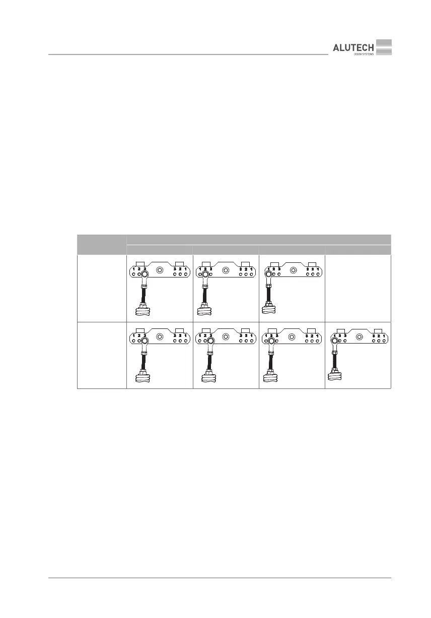
4.2 INSTALLING THE SPRING
Depending on which side of the roadway the barrier will be installed and on the opening direction
of the boom, determine on which side the spring will be installed relative to the lever (Fig. 13).
4.2.1. THE BARRIER IS INSTALLED ON THE LEFT SIDE OF THE ROADWAY,
THEBOOM OPENS TO THE LEFT. THE SPRING IS INSTALLED ON THE LEFT SIDE
Factory setting. To perform such installation of the barrier, determine the correct opening in
the spring lever (Table 3) and adjust the spring if necessary (Fig. 14).
Y
The lever opening in which the spring is inserted by the manufacturer is not nal and must be
checked!
Table 3
BOOM
EFFECTIVE LENGTH L
1
, m
3≤L
1
<4 4≤L
1
<5 5≤L
1
<6 L
1
=6
RBN8 boom
with damper
3
2
1
—
RBN6- boom
3
3
2
1
4.2.2. THE BARRIER IS INSTALLED ON THE RIGHT SIDE OF THE ROADWAY,
THE BOOM OPENS TO THE RIGHT. THE SPRING IS INSTALLED ON THE RIGHT SIDE
To install abarrier in such away, you will need to invert the lever and the spring:
1. Disconnect the spring by unscrewing the spring mounting bolt on the lever (1) (Fig. 15),
and unscrew the lever mounting bolt on the output shaft (2).
2. Screw the spring mounting bolt into the lever (3).
3. Remove the lever by slowly screwing in the bolt (Fig. 16).
4. Turn the lever 90° and install it back. (Fig. 17).
5. Find the correct opening on the spring lever (see Table 3) and secure the spring to the
lever (Fig. 18).
6. Connect the spring to the barrier cabinet at the bottom (Fig. 19).