BOOM BARRIER BV5868 2323
SETUP
7.2 SETTING OPERATION PARAMETERS
Table 15 shows descriptions of settings, values and factory-preset values upon delivery.
Anexample of setting is given in Table 5.
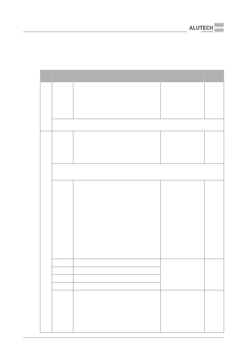
Table 15
MENU SETTING DESCRIPTION VALUES
FACTORY
SETTING
P1
F1
Select boom. The conguration is set to t
the eective length of the boom (Table 3). To
verify that the setting has been selected, see
sub-section 5 ‘Mains connection and open-
close setting’
no — not set
3.0 — 3…4 m
4.0 — 4…5 m
5.0 — 5…6 m
6.0 — 6 m
no.
Y
When P1–F1 settings are changed, the factory-preset values of P5 and P6 menus are set
automatically
P3
F1
Manual operation mode. The movement is
performed when pressing and holding the
control device: OP and CL connection inputs
(Fig.37, terminal block 4). Commands from
remote controls and automatic movements are
not executed, SBS and ALR inputs do not work
no — disabled
on — enabled
no.
Y
In manual mode, the control devices must be located in a place that ensures a good visibil-
ity of the barrier area (boom movement). If access is attempted by unauthorized persons,
any operation by them must be made impossible, e.g. by installing a key switch
F3
Collective operation mode. Depending on
whether the mode is enabled or disabled,
the logic of SBS connection (Fig. 37, terminal
block4) and STEP-BY-STEP inputs of the
remote control (Table 6) will dier.
Enabled: when a command is executed,
the operation sequence will be as follows
Open — Close — Open — Close…
When opening, no commands are executed.
When closing, a command will cause the barri-
er to stop and subsequent full opening.
Disabled: when a command is executed,
the operation sequence will be as follows
Open— Stop — Close — Stop — Open…
no — disabled
on — enabled
no.
F4 Outputs on terminal block 5 (Fig.37)
no — disabled
01…16 — see details
in Table 16
no.
F5 Outputs on terminal block 6 (Fig.37)
F6 Outputs on terminal block 7 (Fig.37)
F7 Outputs on terminal block 8 (Fig.37)
F8
Functioning of SBS and OP inputs (Fig.37,
terminal block 4). When conguring the out-
puts of terminals 5–8 for two-way regulation
(values 05 and 06, Table 16), the SBS input can
be used for the ENTRY direction, the OP input
for the EXIT direction. STEP-BY-STEP or OPEN
commands correspond to those of the remote
control. (Table 6)
01 —
02 —
03 —
SBS step-by-step
OP OPEN
SBS step-by-step
OP OPEN
SBS step-by-step
OP OPEN
01.