BOOM BARRIER BV5868 1111
ELECTRICAL CONNECTIONS
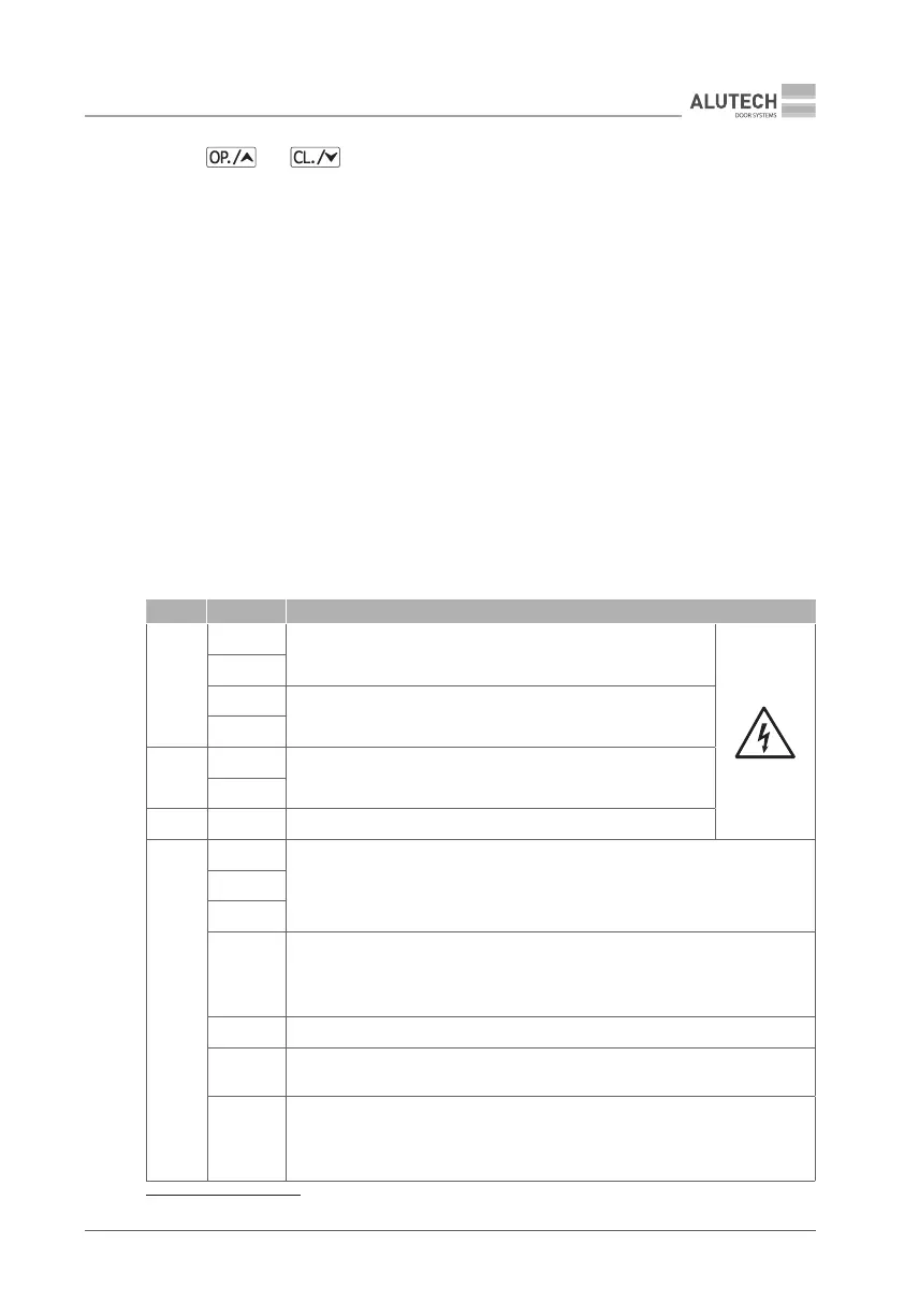
10. Use and buttons of the control unit to make several full cycles of opening
and closing the barrier. Make sure that the boom starts to move and moves smoothly
(without jumping), stops smoothly at the end of the movement and that there is no
impact on the retainer bolt.
11. If necessary, set a different value for the boom length in the settings (section ‘7.2. Setting
operation parameters’, P1–F1) and / or adjust the boom speed when opening and closing
(section ‘7.2. Setting operation parameters’, P6–F1 and P6–F2)
12. Please refer to the relevant sections of the manual for further electrical connections,
additional settings and put into operation.
6. ELECTRICAL CONNECTIONS
Y
When using, installing and connecting additional electrical devices (accessories), observe the
manuals accompanying these devices. Incorrect connection may result in product failure.
Use additional devices (accessories) oered by ALUTECH and with the required characteristics.
ALUTECH is not responsible for the unstable operation of the boom barrier system when using
accessory devices manufactured by other manufacturers.
Location and designation of the contacts are shown in Fig. 37.
Table 4
BLOCK CONTACT DESCRIPTION
1
L
230 V / 50 Hz mains supply
(section ‘5. Mains connection and open / close setting’)
N
NF *
230 V / 50 Hz outputs for primary conductors of the control unit
transformer
LF *
2
L
230 V / 50 Hz outputs for power supply of add-on devices.
Maximum load not exceeding 3 A
N
3 PE Protective earthing connection contacts
4
+BAT
Connection of the special ALUTECH unit with charging module and 24 V DC /
2.4 Ah battery (Fig. 38). The battery pack allows you to open the barrier in an
emergency mode (when the mains voltage is cut o). The time of full charge of
the battery pack is ~48 h at continuous running of the barrier in standby mode
−BAT
BCH
OP
OPEN controller input (Fig. 38, OPEN) with normally open contact (NO). When
activated, the OPEN control command is executed. The behavior can be dierent
depending on the settings made (section ‘7.2. Setting the operating parameters’
P3–F8)
GND Common contact
CL
CLOSE controller input (Fig. 38, CLOSE) with normally open contact (NO).
Whenactivated, the CLOSE control command is executed
SBS
STEP-BY-STEP controller input (Fig. 38, STEP-BY-STEP) with normally open
contact (NO). The STEP-BY-STEP control command (open, stop, close) is executed
when triggered. The behavior will depend on the settings (section ‘7.2. Setting
operation parameters’ P3–F1, P3–F8)
* Connections are performed by manufacturer on delivery.