BOOM BARRIER BV5868 2929
SETUP
4
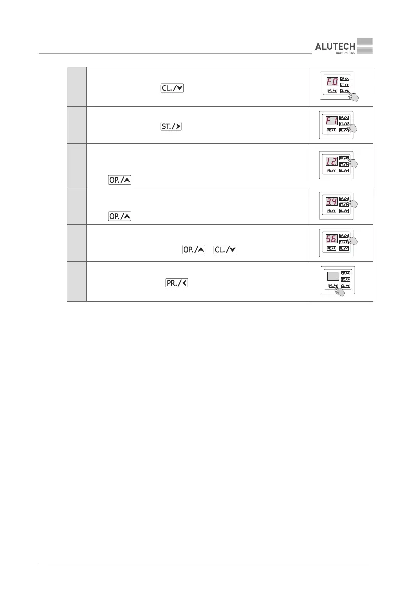
When F0 appears, press button
5
When F1 appears, press button
6
Two digits with two dots (e.g., 1.2.) will be displayed.
These are rst two digits of the counter.
To see the following two digits (third and fourth) of the counter,
press button
7
The following two digits with a dot (e.g., 3.4) will be displayed.
To see the last two digits (fth and sixth) of the counter,
press button
8
The last two digits with a dot at the end (e.g., 5 6.) will be displayed.
To see counter digits again, use or buttons
9
To exit setup menu, press button three times
×3
7.5 TWOWAY TRAFFIC SIGNALIZATION
An example of two-way trac signalization scheme is shown on Fig. 48:
• perform electric connections of two traffic lights as shown in Fig. 46;
• perform electric connections of photocells as shown in Fig. 40;
• configure (see sub-section ‘7.2. Setting operation parameters’) the control unit terminal
blocks outputs for ENTRY (P3–F4–06) and EXIT (P3–F5–05) traffic lights;
• disable the green light of the barrier built-in LED in the settings (P8–F6–01);
• assign OPEN ENTRY (P2–F3–06) and OPEN EXIT (P2–F3–02) commands to two buttons
ofremote controls in the setup;
• set barrier automatic close timeout (P4–F1);
• set barrier automatic close timeout after photocells actuation (P4–F2);
• check that the PHOTOTEST function for the photocells check is enabled (P7–F3–01) in the
settings.
The green trac light will be on when the barrier is fully open for adirection according to the
pressed remote control button (e.g. ENTRY). The trac light in the other direction (e.g. EXIT) will
be red. When the trac light is green driving through the open gate is permitted. The barrier
will close automatically after apreset delay time is out. Recording the OPEN command into the
remote controls provides only opening of the gate while operating aremote control.