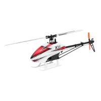
The ALZRC Devil X360 is a high-tech remote-controlled helicopter designed for enthusiasts and experienced pilots. This manual provides comprehensive instructions for assembly, operation, and maintenance, emphasizing safety precautions due to the inherent dangers of RC helicopters.
Function Description
The Devil X360 is a remote-controlled helicopter designed for flight, offering a blend of high-tech design and performance. It requires assembly of various components, including the main rotor, tail rotor, servos, motor, ESC, and gyro system. Once assembled and properly configured, it is capable of controlled flight, including 3D maneuvers for experienced pilots. The helicopter's design incorporates features for stability and precise control, making it suitable for both learning and advanced flying.
Important Technical Specifications
Dimensions and Rotors:
- Main Rotor Diameter: 805mm
- Main Blade Length: 370mm
- Tail Rotor Diameter: 160mm
- Tail Blade Length: 62mm
Shaft Diameters:
- Main Shaft Diameter: 6mm
- Spindle Shaft Diameter: 5mm
- Tail Shaft Diameter: 4mm
- Tail Spindle Shaft Diameter: 3mm
Motor and Battery:
- Motor Size: Maximum 32mm diameter, maximum height 48mm
- Battery Compartment: 34x34x120mm
- Recommended Li-Po Battery: 1400-1600mAh 22.2V 6S (within 34x34x120mm dimensions)
Required Electronic Equipment (Combo/Super Combo versions may include some):
- Transmitter: 6-channel or more, helicopter system
- Receiver: 6-channel or more
- Digital Pitch Gauge
- Brushless Motor: 1800KV 6S 3.5mm spindle (Combo/Super Combo)
- Brushless ESC: 40-60A (Combo/Super Combo)
- Swashplate Servos (x3): Recommended torque 3KG*cm or higher (Super Combo)
- Locked Rudder Servo: Recommended torque above 4kg*cm and speed of 0.06-0.04s (Super Combo)
- 3-Axis Gyro System: (Super Combo)
Gear Ratios (Examples):
- 9T: 14.55:1:4.69
- 10T: 13.10:1:4.69
- 11T: 11.90:1:4.69
- 12T: 10.91:1:4.69
- 13T: 10.07:1:4.69
Usage Features
Assembly:
The manual provides a detailed, step-by-step assembly guide, starting from the servo mounts and progressing through the main frame, landing skid, tail boom, gear assembly, motor installation, and rotor head. Specific instructions are given for applying thread lock, anaerobics retain, grease, and CA glue at various points. It highlights the importance of not overtightening screws into plastic parts and ensuring smooth movement of components.
Pre-Flight Operations:
- Frequency Check: Verify no interference with other RC pilots.
- Battery Check: Ensure transmitter and receiver batteries are sufficiently charged.
- Throttle Position: Confirm throttle stick is at the lowest position and IDLE switch is OFF.
- Power On/Off Procedure: Turn on transmitter first, then receiver; turn off receiver first, then transmitter.
- Movement Check: Verify smooth and correct movement of all controls and servos, checking for interference or broken gears.
- Component Integrity: Inspect for missing or loose screws/nuts, cracked parts, especially on main rotor blades and holders.
- Ball Link Check: Ensure all ball links are secure to avoid poor flight stability.
- Battery Fastening: Confirm battery and power plug are securely fastened to prevent dislodging during flight.
- Gyro System Setup: Carefully set up the 3-axis gyro system without main and tail blades.
- Belt Tension: Check the tension of the tail belt.
- Motor Pulley Gear Ratio: Verify and set the correct revolving speed, with a suggestion not to exceed 3600r/min.
Flight Environment:
- Fly only in safe, open areas, away from people, homes, crowds, buildings, high voltage cables, and trees.
- Choose a legal flying field with flat, smooth ground.
- Use a training skid for initial practice to reduce damage from errors.
- Avoid flying in inclement weather (rain, wind, snow) or darkness.
Control and Handling:
- The helicopter requires a certain degree of skill to operate. Inexperienced pilots should be supervised by experts.
- The manual emphasizes that improper operation or unfamiliarity can lead to serious injury or death.
Maintenance Features
Regular Inspections:
- Periodic Inspection and Replacement: Components like the tail rotor holder should be regularly inspected and replaced as needed.
- Gear Assembly Check: After assembly, ensure the main gear rotates smoothly. If friction is present, adjust by removing washers.
- Tail Rotor Shaft Gap: Check the gap between the tail shaft and tail case, reducing it by adding washers if necessary.
- Head Dampening: For 3D flight or high RPM, consider adding a washer between the damper and bearing. After about 20 flights, manually check head dampening and add a 0.1mm washer if it feels loose.
- General Maintenance: The manual states that the RC helicopter must be regularly maintained.
Component Care:
- Carbon Fiber Parts: Edges of carbon fiber parts can be sharp. It is recommended to de-burr them with sandpaper to prevent cable cuts.
- Plastic Parts: Avoid overtightening screws into plastic parts to prevent damage.
- Moisture Protection: Keep the model and electronic equipment away from moisture and contaminants to prevent malfunctions.
Post-Assembly Checks:
- Factory Assembled Parts: If the product comes with pre-assembled components, always re-check that all parts are firmly secured and glues are applied.
- Motor Gear Alignment: After installation, ensure the motor gear and main gear are aligned.
- Tail Case Level: After tightening screws, check if the tail case is level with the fuselage.
Tools Required for Assembly and Maintenance:
- Hexagon Screw Driver (0.9mm/1.5mm/2.0mm/2.5mm/3.0mm/4.0mm)
- Hex Fork Wrench (5.5mm/7.0mm)
- 243 Thread Lock
- 648 Anaerobics Retain
- Grease
- CA Glue
- Scissors
- Cutter Knife
- Diagonal Cutting Pliers
- Needle Nose Pliers
- Circlip Pliers
- Sand Paper
- Soldering Equipment