9
Centerline of cabinet
top cutout
B
A
C
D
E
F
G
H
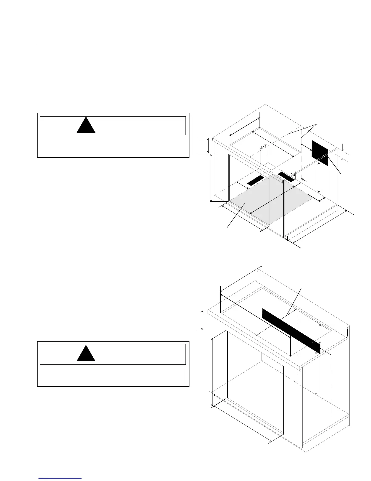
Illustration shows dimensions for venting behind, and to
the left side of the wall oven. Left side venting for wider
island applications only. Junction box and 10
1
/8"x3
3
/8" vent
location for 10"x3
1
/4" vent indicated in black. Grey shaded
area indicates wall oven floor
WARNING
To avoid property damage or personal injury,
information in these installation specifications must be
followed exactly.
A—6" Right of centerline
B—4
1
/2" From top of countertop
C—24" From bottom of oven cutout to bottom jucntion
box location
D—3
1
/2" minimum from back wall of island cabinet and
back of wall oven
E—28"minimum island depth
F—23
1
/2" Bottom of wall oven in cutout
G—28
1
/2" wall oven cutout width
H—27
1
/4" wall oven cutout height
I— 3
1
/2" minimum from side wall of island to side wall of
oven
J— 6" from back of cooktop cutout to back of vent
cutout
K—4
7
/32" from centerline to vent cutout
L—28
7
/8" cooktop cutout width
M—20
5
/8 “ cooktop cutout depth
N—4
1
/2" from top of countertop to top of wall oven cutout
B
A
C
Junction
box
location
D
E
F
G
H
I
J
Centerline of
island
top cutout
K
L
Shaded area
represents
bottom of
wall oven
M
N
AK2H36, AK2T36, 36" Electric Cooktop
Installed Above AOES3030 Wall Oven
Cooktop and wall oven junction box location indicated in
black.
WARNING
To avoid property damage or personal injury,
information in these installation specifications must be
followed exactly.
A— 4
1
/2" minimum from top of countertop
B— 8" maximum from right side wall of wall oven cutout
C— 24" minimum from bottom of cutout
D— 28
1
/2" wall oven cutout width
E— 27
1
/4" wall oven cutout height
F— 34
1
/8" cooktop cutout width
G—20
3
/4" cooktop cutout depth
H— 3
3
/16" from top of countertop to top of wall oven
cutout
AKED3060 or AKES3060 Downdraft Cooktop Above AOES3030 Wall Ovens in an Island
Application
 Loading...