Structure and function
Cirrus 03 BAH0101-05 11.19
105
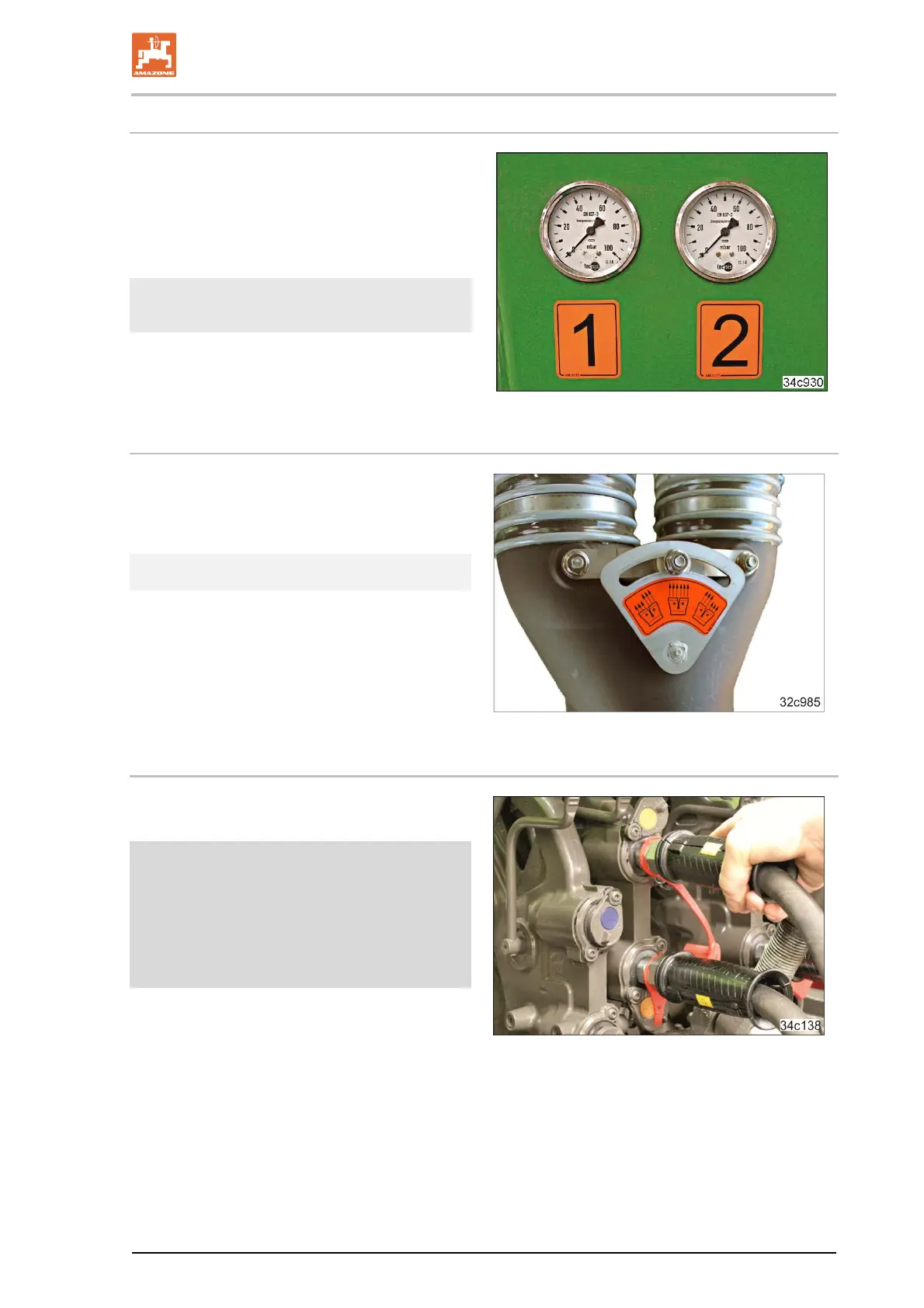
Pressure monitoring in the two chamber hopper
If the implement is equipped with a hopper with
two chambers, an overpressure is generated in
the hopper by the running fan.
The pressure gauges (Fig. 119) on the front wall
of the implement show the air pressure in the
chambers 1 (front) and 2 (rear).
Fig. 119
The pressure difference must not be greater
than 5 mbar.
If the required air pressure is not reached, check
the system for leaks. Amongst other things,
check if the hopper cover is closed.
Air distributor
Implements with a two-chamber hopper and two
distributor heads are equipped with an air
distributor. The air distributor is used to set the
same amount of air in both conveyor sections.
Fig. 120
Do not change the factory settings.
5.16.3 Connecting the blower fan to the tractor hydraulics
The blower fan hydraulic motor may be
connected to the tractor hydraulic system.
Fig. 121
Set the blower fan speed
at the flow control valve of the tractor
(see chapter 8.9.1)
at the pressure relief valve of the hydraulic
motor, see chapter 8.9.2,
if the tractor has no flow control valve.
 Loading...