VCU118 Board User Guide 16
UG1224 (v1.5) March 15, 2023
Chapter2: Board Setup and Configuration
Installing the VCU118 Board in a PC Chassis
Installation of the VCU118 board inside a computer chassis is required when developing or
testing PCI Express® functionality.
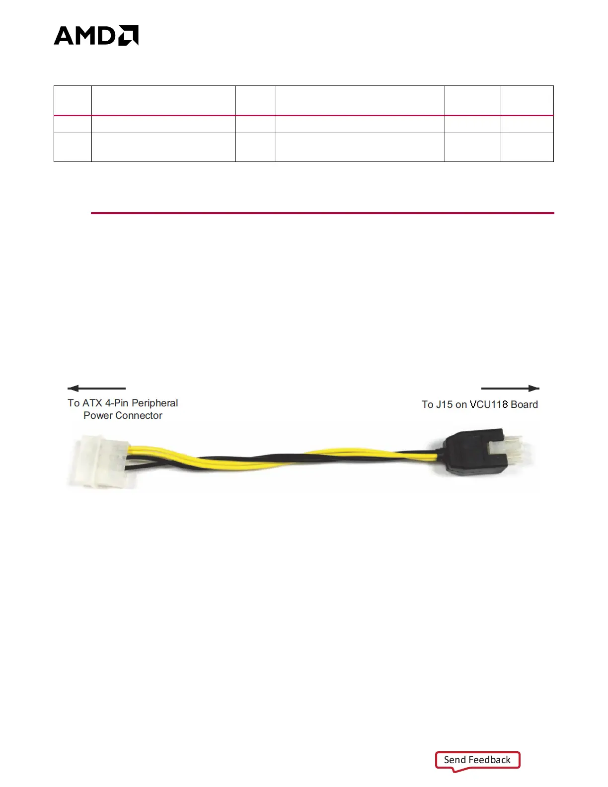
When the VCU118 board is used inside a computer chassis (that is, plugged in to the PCIe®
slot), power is provided from the ATX power supply 4-pin peripheral connector through the
ATX adapter cable (Figure 2-3) to J15 on the VCU118 board. The AMD part number for this
cable is 2600304. See [Ref 29] for ordering information.
To install the VCU118 board in a PC chassis:
1. On the VCU118 board, remove the six screws retaining the six rubber feet with their
standoffs, and the PCIe bracket. Reinstall the PCIe bracket using two of the previously
removed screws.
2. Power down the host computer and remove the power cord from the PC.
3. Open the PC chassis following the instructions provided with the PC.
4. Select a vacant PCIe expansion slot and remove the expansion cover (at the back of the
chassis) by removing the screws on the top and bottom of the cover.
J29
(1)
BPI Flash A25 source select 1-2 A25 connected to FPGA U1 pin BE17 7 54
J110
Zynq 7000 SoC System
Controller U111 QSPI_IO3
Off
QSPI_IO3 P/U w/20K (On = P/D to
GND)
847
Notes:
1. Pre-Rev. 2.0 VCU118 boards only.
Table2‐3: Default Jumper Settings (Cont’d)
Jumper Function Default Comments
Figure 2‐2
Callout
Schematic
Page
X-Ref Target - Fig ure 2-3
Figure2‐3: ATX Power Supply Adapter Cable