5-10 | Model 931S / Model 932S UV Analyzers
When performing current or voltage calibration, do not enable (check)
Limit 4...20 mA after calibration is complete.
To calibrate the current outputs:
1. Measure the Zero (low-scale) signal of each output:
a. Click the Zero Cal button to change its status to On. The status of
Normal, Mid-Scale, and Span Cal should be Off.
b. Connect a current meter to Pins 1 and 2 (at J109 on the Customer
I/O board) and measure the current of Output 1. Under Current
Outputs, enter the value next to Zero (mA), under the first column
(Output 1). Place a 250 Ohm resistor in series of the multi-meter
for accurate calibration.
Analog Output Calibration
Current Calibration
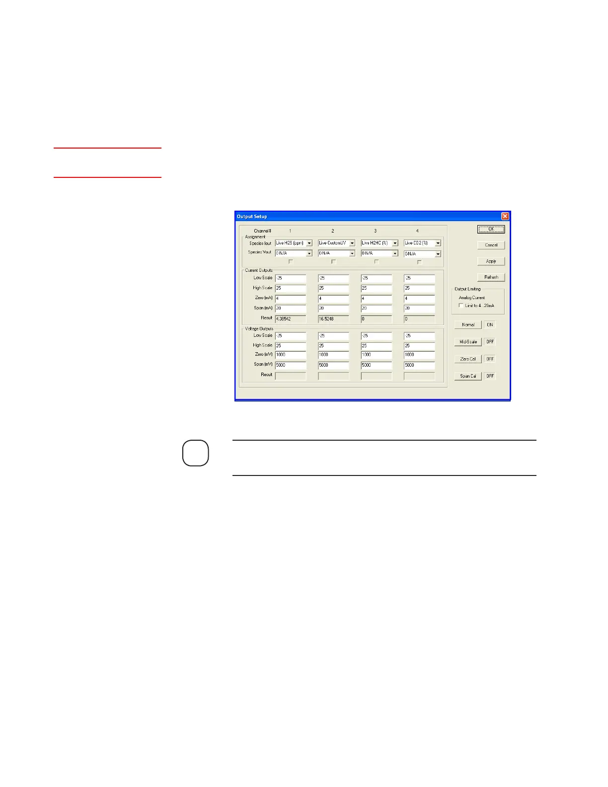
The current outputs are calibrated at the factory. If a current output
module is replaced or added, calibrate that output. This is done from the
Output Setup dialog box. Calibration of a current output is performed by
entering the measured low-scale (Zero) and full-scale (Span) signals for
each output (see Figure 5-5). These values are used to offset the output to
the correct values.
Figure 5-5.
Output Setup dialog
box, with two streams
(Model 932S).
Setup (tab)Output
NOTE

 Loading...


