Controller / User Interface | 4-9
General Tab
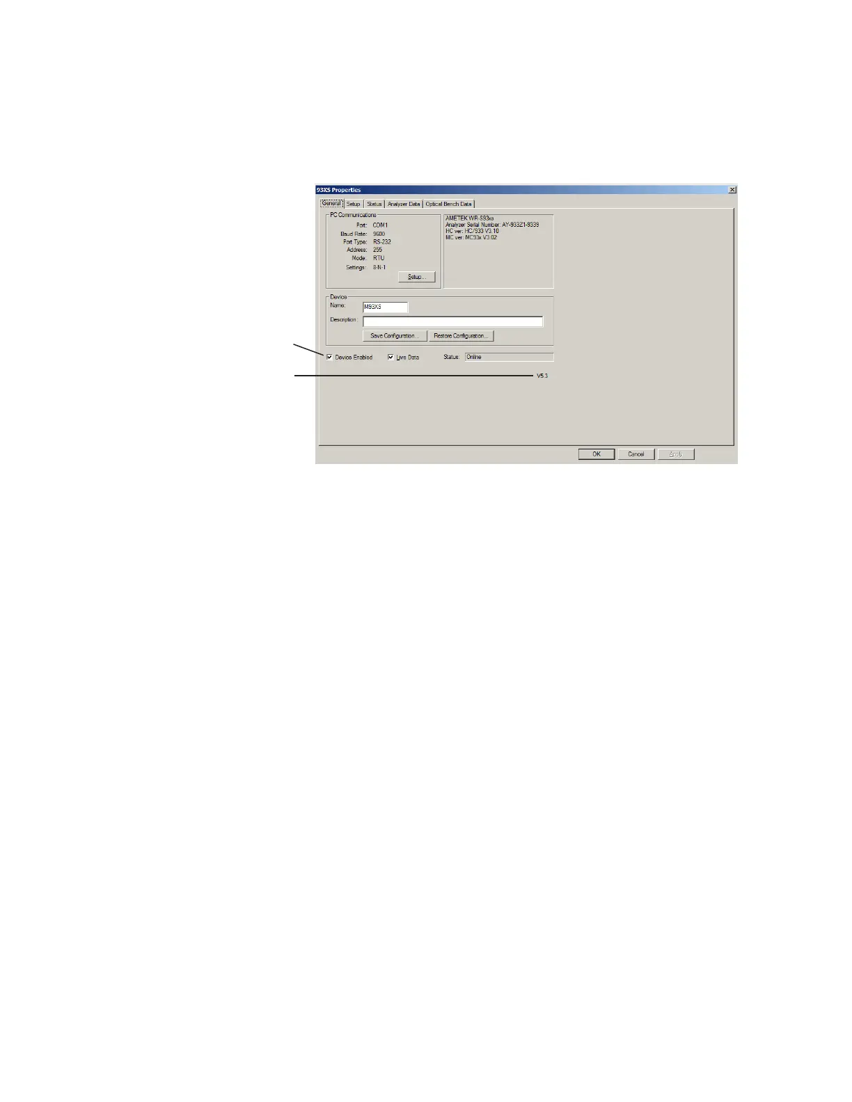
When the analyzer is connected to the PC, the current Host Controller
and Microcontroller Firmware Version Number and analyzer Serial
Number are displayed to the right of PC Communications (Figure 4-1).
Other parameters include:
PC Communications
Displays information that has been configured from the
Communication Settings dialog box.
Setup
Allows you to set up the communication parameters required to
establish communication with the analyzer (see “Modbus Serial /
Modbus TCP Communication Setup” in this chapter).
Device
Name
Enter a tag name or number.
Description
Enter a description to further define the analyzer, such as a Tag
Number or location in the plant.
This can be useful if using a Multi-Drop system, where multiple
analyzers are wired together on the same line. In this case, you can
assign different names and descriptions for each analyzer.
Figure 4-1.
General tab
(with Modbus Serial
communication settings).
Congurator Software Version
Check box selected

 Loading...


