Installation and Start-Up | 3-43
4. Disconnect the Vent tubing from the analyzer and plug it with a cap
fitting.
Open the Metering Valve and the Sample Flow Pressure Regulator
(regulator closest to the Sample Shut-Off Ball Valve on the Sample
Inlet line).
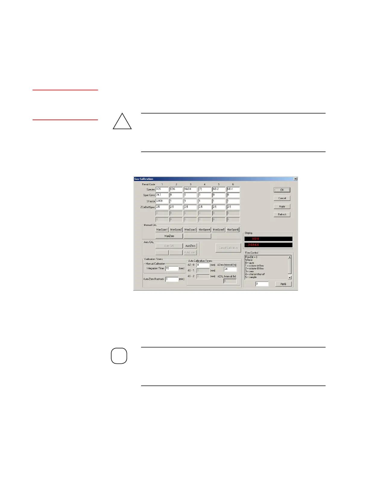
5. Using the Configurator Software, change the Flow Control to ‘2’
(zero). Click OK then Apply. Do not save the changes to EEPROM.
If the optional pressure transducer is installed do not set the pres-
sure higher than its upper pressure rating. Refer to Final “As-Built”
drawings in the analyzer Documentation Package for details about the
pressure transducer rating.
!
CAUTION
Setup (tab)
Gas Calibration<<Flow
Control>>
6. Use the Zero/Aspirator Pressure Regulator to pressurize the sample
system to 70 KPA (10 PSI) higher than the recommended sample
pressure.
The Sample Pressure Gauge and the Zero Gas Pressure Gauge must
be set at the same pressure to avoid one leaking into the other. Adjust
the Zero Gas Pressure Regulator until these pressure readings are the
same.
NOTE
Figure 3-21.
Gas Calibration dialog
box (Model 932S).

 Loading...


