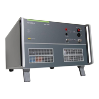
1 Frame Bus
Daisy Chain bus with Sub D 15 poles male and female connectors. This port is used as communication and
control bus between EM Test devices.
2 Reference earth connection
The generator has to be connected to the reference earth plane of the test set up.
3 Signal OUT
Control output to system dc source (normally VDS200N). The control signal is generated in the AutoWave or
AMP 200 internal and pass through the AMP200N to the “analog IN” of the VDS200N.
4 CH 1 IN
BNC input -10V to +10V: This input is used for controlling the VDS 200 or internal amplifier. In switch off
Status the connection is passing to the Signal out output.
5 CH 2 IN
BNC input -10V to +10V to internal amplifier.
6 Offset OUT
Output control signal from the AMP 200N internal DC source (-10V to +10V).
7 Ventilation
The cooling output needs at least 20cm space for a free airflow.

 Loading...