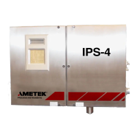
46 | IPS-4 Zone1/Analyzer
Record the initial sample response time in a log book, as described under
“Recording Initial Readings,” later in this chapter.
15. For systems using an Aspirator:
Adjust the Aspirator Pressure Regulator to achieve normal operating
flow rates as described under “Adjusting the Sample Flow Rate,” later
in this chapter. The optional Flow Indicator (or meter), if used, will
provide a visual indication of sample flow.
16. Close and secure the analyzer doors.
The start-up and verification checks are complete and the analyzer is
ready for normal operation.
Start-Up Diagnostic Checklist
This checklist describes problems that can be encountered while powering
up the analyzer and/or preparing it for normal operation. If the analyzer
experiences problems during power-up, review this checklist and perform
the corresponding corrective action to fix any problems.
Problem Encountered
Status/error code conditions for current alarms are displayed on the
User Interface Panel.
Corrective Action
To view current alarms, press the ALARMS soft key to view the
ALARMs screen. For information about viewing current alarms, refer
to “Alarm Notification (HOME Screen)” and “ALARMS Menu Screen”
in Chapter 4. For detailed information about these alarms, refer to the
alarm conditions and corrective action in the “Maintenance & Trouble-
shooting” chapter of this manual.
Figure 13.
HOME screen
(example).
Measure
► Heater 21 °C
Bench 20 °C
Cell 23 °C
HOME ALARMS STATUS SETUP

 Loading...


