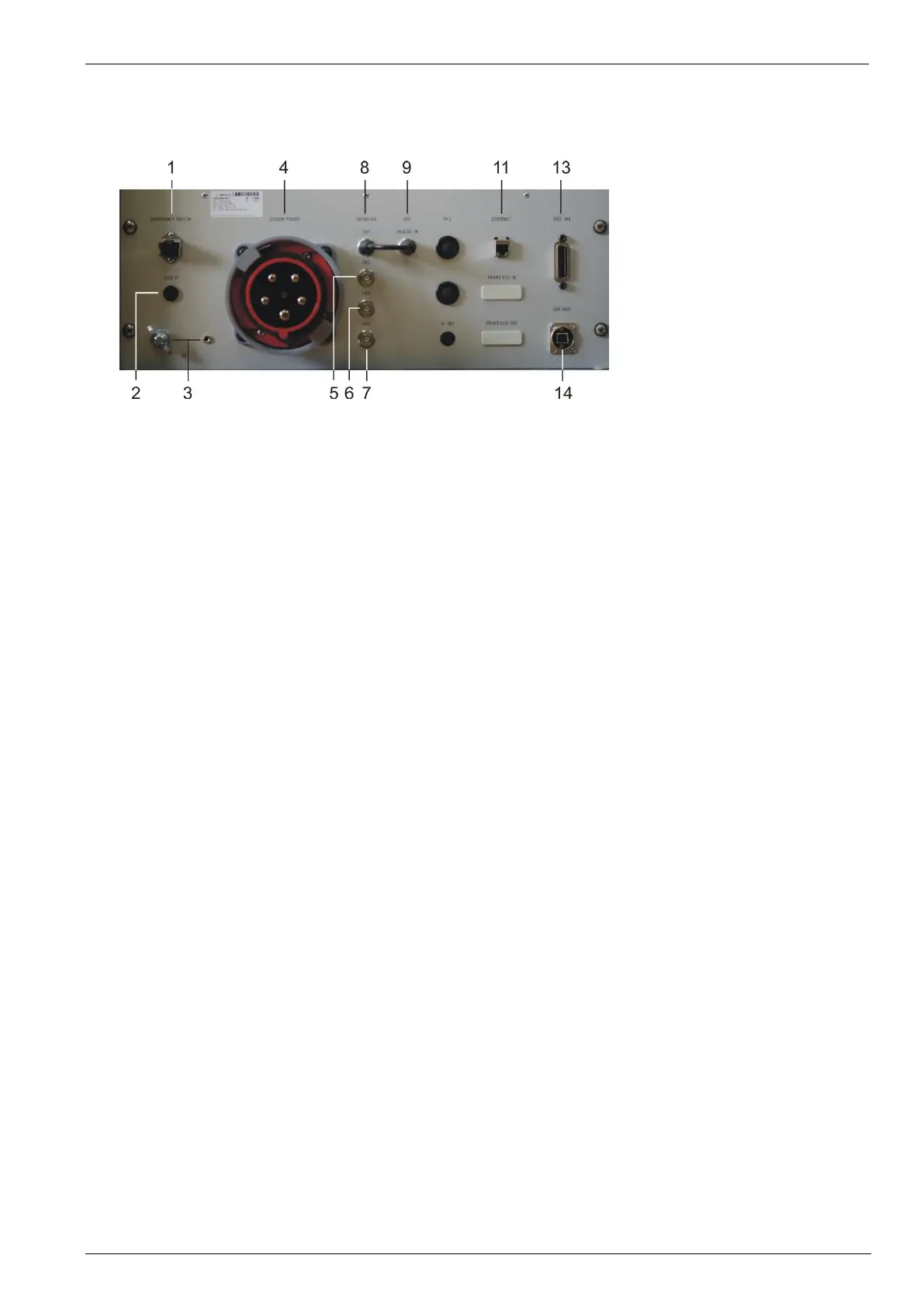
1 Emergency Switch
Used to connect the emergency lockout switch.
2 Fuse
See 5.5 General, and 4.2 Fuses
Note: On the 208V models, this is replaced by an additional mains connector for countries where 100-120V mains is the
norm. In this case, be sure to connect this to mains.
3 Reference earth connection
During immunity tests, it may be useful to connect the simulator with reference earth plane of the test set-up.
For complete rack installations, all different test generators shall be grounded at this point.
4 Mains input
This connector depends on the VDS model
5-7 Optional AutoWave Outputs
Can be used to connect the AutoWave with additional sources
8 AutoWave CH1 Output
Not present on some units when connected internally
NOTE: If equipped with a CH1 output, the supplied BNC bridge must be connected to Analog In to the VDS
9 Analog In to VDS
Connection to AutoWave or an external arbitrary waveform generator if needed.
10 Optional Framebus In
The framebus is usually taken from the AutoWave
11 Ethernet connection pass-through for AutoWave (if equipped)
12 Framebus Out
Be sure to use the supplied Framebus terminator 101732
13 IEEE 488 // GPIB
IEEE 488 interface with IEEE connector.
14 USB interface
USB interface “USB B” connector. For data transfer a USB interface is available. The internal RS 232 interface
is converted to USB standard. Therefore, the user must set the same Baudrate in the device and control
software.
Note: USB interface is for controlling the VDS 200Q in stand-alone configuration. See the PFM 200N200 and
AutoWave manuals if alternative configurations will be used. AutoWave, doesn’t support USB communications.
 Loading...