0.6 (2019–07–25)
Amlogic Proprietary and Confidential
Copyright © Amlogic. All rights reserved.
62
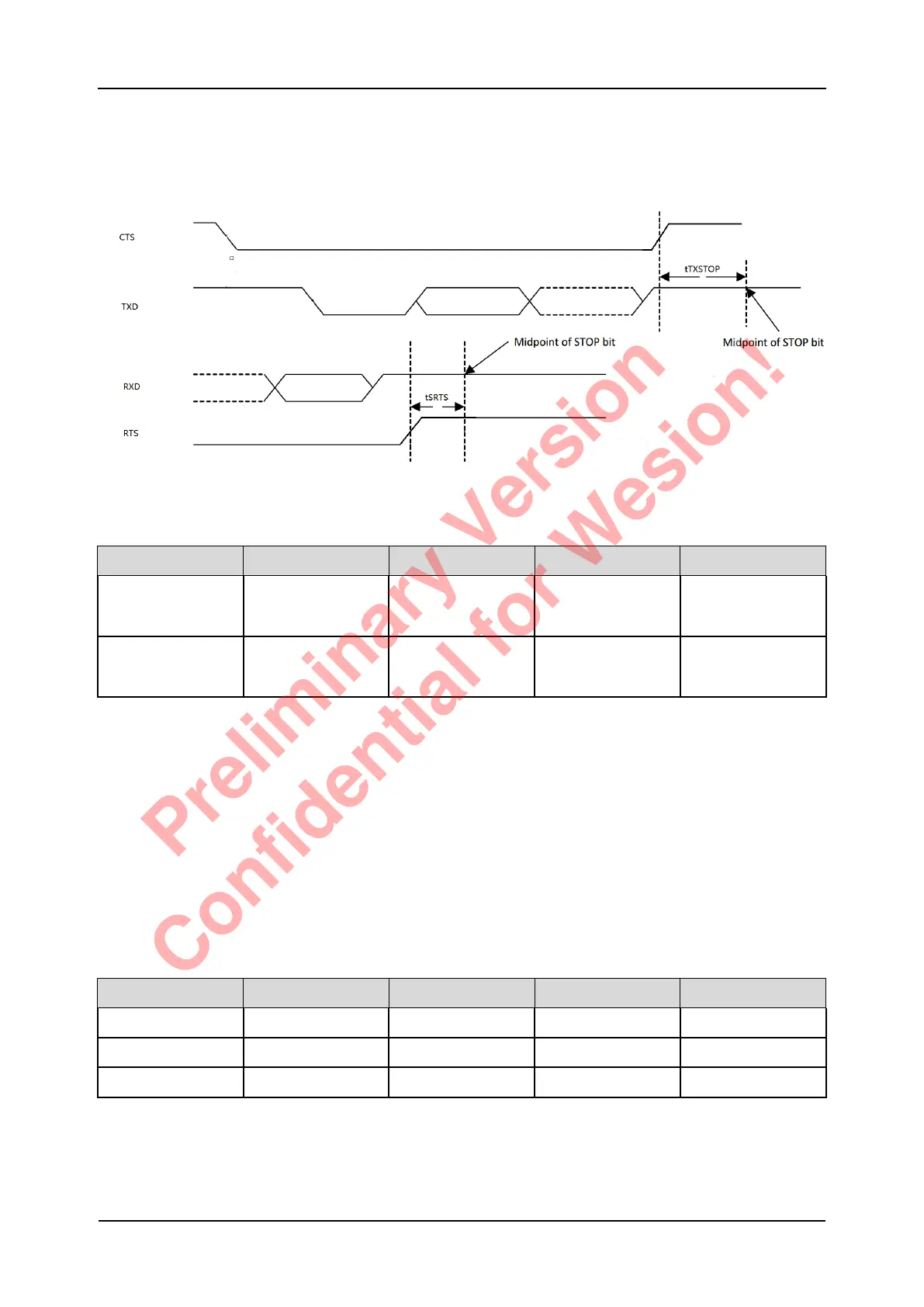
5.7.9 UART Timing Specification
Figure 5-21 UART Timing Diagram
Table 5-17 UART Timing Specification
Parameter Symbole Min. Max. Units.
Delay time, CTS
high before midpoint
of stop bit
tTXSTOP - 0.5 Bit Periods
Delay time, midpoint
of stop bit to RTS
hgih
tSRTS - 0.5 Bit Periods
5.8 Power On Config
3 Boot pins are used as power on config (POC) pins, to set the booting sequence.
POC setting is latched at the rising edge of reset signal.
3 POC pins are all pull high internal, CPU will try to boot from nand/eMMC first, if fails then try to boot
from SD CARD, still fails then try to boot from USB (PC).
External 4.7K ohm pull down resistors can be used to change the POC setting. The resistors should
be placed on right location, avoid stubs on high speed signals.
The SoC’s Power On Configuration is listed as following:
Table 5-18 Power On Configuration Pin Table
POC Boot Pin Name Pull low Pull high
POC_0 Boot_4 SPI NAND First SPI NAND boot first Default sequence
POC_1 Boot_5 USB First USB boot first Default sequence
POC_2 Boot_6 SPI NOR First SPI NOR first Default sequence
S905D3 Quick Reference Manual 5 Operating Conditions
Preliminary Version
Confidential for Wesion!