0.6 (2019–07–25)
Amlogic Proprietary and Confidential
Copyright © Amlogic. All rights reserved.
61
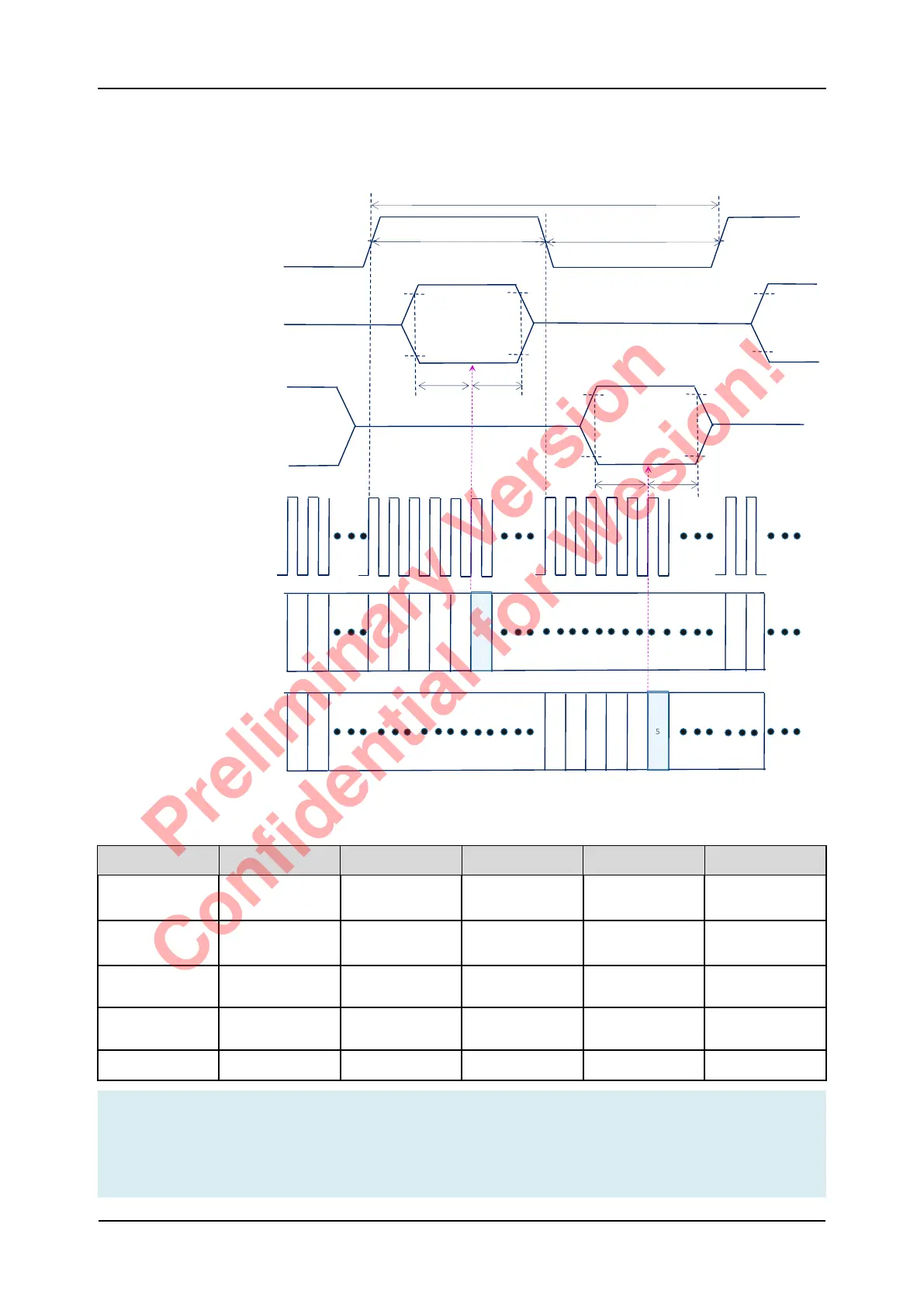
5.7.8 PDM Timing Specification
Figure 5-20 PDM Timing Diagram
Table 5-16 PDM Timing Specification
Parameter Symbol Min. Typ. Max. Units.
PDM clock
period
tDCLK 200 ns
PDM clock duty
cycle
tHIGH/tLOW 48% 52% tDCLK
PDM Data setup
time
tSETUP 20 ns
PDM Data hold
time
tHOLD 20 ns
Sys clock period tSYSCLK 5 7.5 ns
Note
1. Default PDM_SYS_CLOCK=133MHz.
2. For Sample position, please refer to PDM register PDM_CHAN_CTRL, PDM_CHAN_
CTRL1.
SELECT=H
SELECT=L
SELECT=H
T=1/fCLOCK
50%
50%
50%
T/2
T/2
Vih
Vil
Vih
Vil
Vil
Vih
High Z High Z
High Z
SELECT=L
High Z
PDM_DCLK
PDM_DIN
( SELECT=VDD )
PDM_DIN
( SELECT=Ground )
0
1
Sample point
Sample point
PDM_SYS_CLOCK
(SOC Internal)
Sample Position
( SELECT=VDD )
0
1
2
3
4 5
Vih
Vil
tSETUP
tSETUP
tHOLD
tHOLD
Vih
Vil
0
1
2
3
4
5
Sample Position
( SELECT=Ground )
S905D3 Quick Reference Manual 5 Operating Conditions
Preliminary Version
Confidential for Wesion!