0.6 (2019–07–25)
Amlogic Proprietary and Confidential
Copyright © Amlogic. All rights reserved.
63
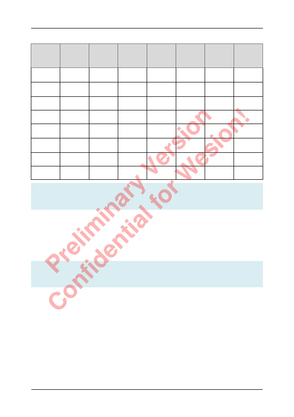
Table 5-19 Booting Sequence Diagram
No. POC_0
(SPI_
NAND)
POC_1
(USB_
BOOT)
POC_2
(SPI_NOR,
eMMC/
NAND )
1st Boot
device
2nd Boot
device
3rd Boot
device
4th Boot
device
1 0 0 0 USB (short
delay)
SPI_NOR NAND/
eMMC
SD Card
2 0 0 1 USB (short
delay)
NAND/
eMMC
SD Card -
3 0 1 0 SPI_NOR NAND/
eMMC
SD Card USB
4 0 1 1 SPI_NAND NAND/
eMMC
USB -
5 1 0 0 USB (short
delay)
SPI_NOR NAND/
eMMC
SD Card
6 1 0 1 USB (short
delay)
NAND/
eMMC
SD Card -
7 1 1 0 SPI_NOR NAND/
eMMC
SD Card USB
8 1 1 1 NAND/
eMMC
SD Card USB -
Note
If GPIOC is not work as SDIO port, please do not pull CARD_DET(GPIOC_6) low when system
booting up, to avoid romcode trying to boot from SD CARD.
5.9 Power On Reset
The POR (Power On Reset) monitors VDDIO_AO power voltage and compares it to a threshold
Voltage.
RESET_N pin is low (SOC is reset mode) when VDDIO_AO is below threshold,
Force SOC enter reset mode via key to GND serial 100R resitor.
Note
1. Place 1nF capacitors on RESET_N Pin.
2. VDDIO_AO power pin is only support 3.3V,not allow to power off in sleep mode.
S905D3 Quick Reference Manual 5 Operating Conditions
Preliminary Version
Confidential for Wesion!