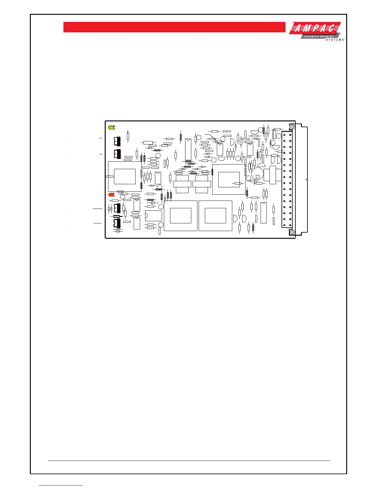
8.5.5 Microphone / BGM Mixer Board
The microphone preamplifier board accepts inputs from the Panel MIC via a microphone preamp
(302-475), Remote Paging Console and two BGM Inputs. The microphone inputs operate with a
compression circuit to compensate for varying input levels. Level adjustments for both the main and
remote microphones are provided to allow the user to set the system up for the specific requirements
of the installation. The BGM inputs are provided with level controls and will be muted to all zones
when:
OWS is operating from batteries
Alarm signal is received in automatic or manual mode
In manual mode and the zone control switches on the ECP are selected
Note: The background music is restored ONLY following a MASTER RESET operation.
Figure 9: 302-4840 Microphone / BGM Mixer
8.5.6 Standby Microphone / BGM Mixer Board
This board provides a complete duplicate of the main Microphone/BGM board and is automatically
switched in when the system detects a failure in the main board. The Microphone fault indicator is
also illuminated.
If level adjustments are required first remove the main Microphone/BGM Mixer.
8.5.7 FACP Input CPU Board
This board interfaces all the hard wired FACP inputs into the EV3000 Main CPU. When the EV3000
is installed with an AB3000 this board is not installed. The secondary CPU has an address setting
which is factory set and should not be field adjusted.
8.5.8 Main CPU
The Main CPU is responsible for the total control of the OWS and OIS, the communication with other
ECP’s, remote paging consoles, FireFinder and houses the program module.
The Main CPU has an Address setting that is factory set by way of a dipswitch. It also has another
dipswitch which controls the time from alert to evacuation modes whilst in automatic. This time can
be adjusted on site if required.
8.5.8.1 Program Eprom's
The EPROM's are located on the Main CPU and are responsible for the zoning of the FACP and
EAID inputs and are programmed for each building.
The type of evacuation sequence and the outputs for the visuals are also controlled by the program
EPROM's.
8.5.9 Amplifier Rack Frame
Each Amplifier Rack Frame houses eight (8) 40 Watt zone amplifiers or four (4) 120 Watt amplifiers.
Each frame has a motherboard (302-4760) which provides all necessary connections for the