EasyManuals Logo

Ampac EV3000 User Manual

Ampac EV3000
54 pages
To Next Page IconTo Next Page
To Previous Page IconTo Previous Page
Page #25 background imageLoading...
Page #25 background image
Page 21
EV3000
INSTALLATION & COMMISSIONING
8.5.16 Power Supply
The Power Supply is supplied in two possible formats these are:
1. G0012 Modular Power Supply.
The G0012 Power Supply is constructed in two sections. These are a rectifier chassis mounted on
the backpan and a regulator chassis mounted in the rack frame.
The rectifier chassis provides an unregulated DC which is then regulated by the regulator chassis to
provide 27V DC to run the system and charge the batteries. The chassis also houses the 8V
regulator required to provide the 8V DC requirement of the system.
The regulator chassis is modular in construction provides for up to four 27VDC modules, each able
to deliver 8 A. Each module is adjusted in the factory and no attempt should be made to alter these
adjustments.
2. G0018 Power Supply.
The G0018 Power supply is used only on smaller systems and SECP's and is mounted on a chassis
on the backpan. It contains all componentry required to supply 27V to charge the batteries etc and
also provide 8V for the microprocessor circuitry. As in the case of the G0012 all voltages are factory
set and no attempt should be made to alter these settings.
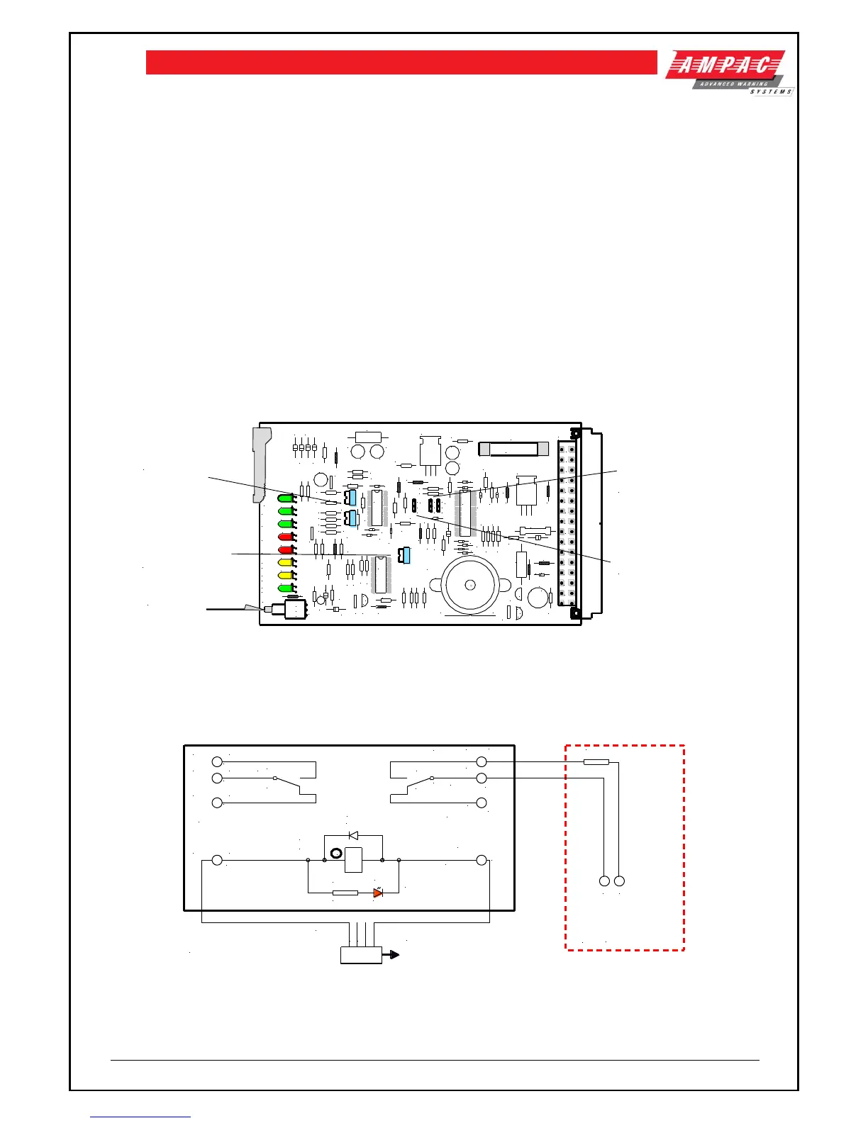
3. Power Supply Supervisory Board
This board monitors the power supply/s, the battery isolated function, power supply temperature/s
and initiates fan forced cooling as required.
ISOL
ON
ROLYTE
RED BLACK
RO7
RO2
RO3
RO1
RO10
RO5
RO4
RO6
RO8
RO11
RO9
3
2
1
LK2
3
2
1
LK1
D13
D11
R29
R30
R14
D14
D12
+
+
C9
R46
R31
R32
+
C7
+
C6
D10
D9
D8
R15
R19
+
C3
+
C2
Q3
IC2
IC1
IC4
D7
LED8
FANS
LED7
BATT
LED6
ELECT-
LED5
LOW V
LED4
HIGH V
LED3
POWER
LED2
MAINS2
LED1
MAINS1
IC3
F1
1 AMP
N/C
C
N/O
SW1
FAN TEST
BUZZER
32
30
28
26
24
22
20
18
16
14
12
10
8
6
4
2
c a
CN1
R33
R26
R27
R9
R2
R12
R13
R7
R11
+
C4
R8
R3
R4
R1
R5
R34
R35
C10
D5
D4
D2
D3
R55
D20
R6
R43
R44
R53
C8
D15
R36
R37R38
R39R40
D1
D16
D17
D18
D19
ZD1
R56
R41
R42
b
c e
Q2
R47
R45
R51
R50
R18
R21
R22
R48
R52
b
c e
Q5
R49
RV1
HIGH V
RV2
LOW V
RV3
C1
R23
R24
b
c
e
Q4
+
C11
C5
R28
R25
1
2
3
LK3
D21
D6
PUSH AND HOLD TO TEST
COOLING FAN OPERATION
SINGLE P/S OPERATION
INSERT LK1 & REMOVE LK2
DUAL P/S OPERATION
INSERT LK1 & LK2
INSERT LK1 IF ELECROLYTE
TESTING OPTION IS UTILISED
RV1 & RV2 ARE FACTORY
SET AND SHOULD NOT
BE ADJUSTED
RV3 - WITH THE BATTERY
FUSE REMOVED ADJUST
ANTI - CLOCKWISE UNTIL
INTERMITTENT BUZZER
OPERATION CEASES.
Figure 16: Power Supply Supervisory Board Layout
8.5.17 Fault Relay
The EV3000 has a fault relay which is normally operated. Should a fault occur in the EV3000 the
relay releases and the Warning System output of the FireFinder recognises and responds to the
fault.
1
2
3
4
CN1
CON1879 4PIN PANDUIT
4
TB1D
+VE
3
TB1C
N/C
2
TB1B
COM
1
TB1A
N/O
4
TB2D
N/O
3
TB2C
COM
2
TB2B
N/C
1
TB2A
-VE
D1
1N4004
4
RL1A
MR62
13
RL1B
MR62
RL1C
MR62
R1*
2K2
D2*
RED
*LED INDICATOR
OPTIONAL
302-763
To CN18 of Master Control
Panel 302-479b of EV3000
10K
TB5
WARN SYS
Fire Finder
302-673
+
-
Note: Only used in a combination
EV3000/FireFinder Panel
N
Figure 17: EV3000 Fault Relay Wiring to the FireFinder

Table of Contents

Other manuals for Ampac EV3000

Questions and Answers:

Question and Answer IconNeed help?

Do you have a question about the Ampac EV3000 and is the answer not in the manual?

Ampac EV3000 Specifications

General IconGeneral
BrandAmpac
ModelEV3000
CategoryControl Panel
LanguageEnglish

Related product manuals